ASM80 Handbook

Introduction

What is ASM80

ASM80 is a browser-based integrated development environment (IDE) designed specifically for assembly language programming of vintage 8-bit CPUs. It provides everything you need to write, assemble, debug, and export programs for classic processors — all within your web browser.

Browser-Based IDE

Unlike traditional desktop assembler tools, ASM80 runs entirely in your browser:

  • No installation — simply visit asm80.com and start coding
  • IndexedDB storage — your files are stored locally in your browser’s database
  • Cross-platform — works on any device with a modern browser
  • Instant compilation — assemble your code with a single keystroke

Integrated Toolchain

ASM80 bundles everything you need in one package:

  • Assembler — powerful two-pass assembler supporting multiple CPU architectures
  • Emulator — built-in CPU emulation for testing your code
  • Debugger — step-through debugging with register and memory inspection
  • Module system — create relocatable modules and libraries

Multi-CPU Support

One IDE supports multiple processor architectures. Write code for different CPUs without switching tools.

CPU Directive Value Notes
Zilog Z80 Z80 SNA, TAP, COM output supported
Intel 8080 8080 COM output supported
Intel 8085 8085
Intel 8008 8008 .a08 extension
MOS 6502 6502 PRG output supported
WDC 65816 C65816
Motorola 6800 M6800
Motorola 6809 M6809
Hitachi HD 6309 H6309
RCA CDP1802 CDP1802

Key Differentiators

ASM80 differs from desktop assemblers in several important ways:

  • Instant compile — press F9 and see results immediately
  • Integrated emulation — test your code without leaving the IDE
  • Sharable projects — share your work via remote projects or ZIP export
  • Visual debugging — see registers, memory, and execution in real-time
  • Module libraries — build and reuse code across projects

Two-Pass Assembler

ASM80 uses a two-pass assembly model:

  1. Pass 1 — builds the symbol table by scanning all code and recording label definitions
  2. Pass 2 — generates machine code using the symbol table to resolve all references

The assembler performs up to 5 iterations of pass 1 to handle forward references — labels used before they are defined. This allows you to write code in any order without worrying about declaration order.

Remote Projects

While most users work with local files stored in IndexedDB, authenticated users can also use remote projects stored on the ASM80 server. Remote projects enable:

  • Access your code from any device
  • Share projects with others
  • Automatic synchronization between devices

See Remote Projects for details.

Getting Started

Getting Started

This guide walks you through creating your first ASM80 project and compiling your first program.

Opening ASM80

Simply navigate to asm80.com in your web browser. The IDE loads immediately — no login required for local development.

Guest vs. Authenticated Use

Guest Mode

Without an account, you can:

  • Create and edit local files
  • Compile and debug code
  • Export projects as ZIP files

Your files are stored in your browser’s IndexedDB. They persist until you clear browser data.

Authenticated Mode

With an account (Auth0 authentication), you additionally can:

  • Create and manage remote projects
  • Sync projects across devices
  • Share projects with others via URL

Creating Your First File

  1. Click the + button in the file tree (left panel)
  2. Enter a filename with the appropriate extension:
    • .z80 — Z80 syntax
    • .asm — generic assembler (CPU set by .cpu directive)
    • .a80 — Intel 8080 / 8085
    • .a65 — MOS 6502
    • .a09 — Motorola 6809
    • .h09 — Hitachi HD 6309
    • .a68 — Motorola 6800
    • .a18 — RCA CDP1802
    • .816 — WDC 65816

Tip: The file extension determines syntax highlighting in the editor. The actual CPU is set by the .cpu directive in your source code.

Writing Your First Program

Create a file called hello.z80 and enter this minimal Z80 program:

.cpu Z80
.org 0x8000

start:  LD A, 'H'        ; Load 'H' into accumulator
        OUT (1), A       ; Output to serial data port
        LD A, 'i'        ; Load 'i'
        OUT (1), A
        HALT             ; Stop execution

.ent start                ; Entry point for debugger

This program:

  • Sets the CPU to Z80
  • Sets the origin address to 0x8000
  • Outputs two characters to the serial data port (port 1 in hello.emu)
  • Halts execution

Compiling

Press F9 or click the Compile button in the toolbar. The assembler runs in a Web Worker, so the editor remains responsive during compilation.

Reading the Output Log

The output log appears at the bottom of the IDE.

Successful Compilation

[10:23:01] Compiling hello.z80...
[10:23:01] OK — 42 bytes, entry point 0x8000

Compilation Errors

Errors are shown in red with the file name and line number:

[10:23:05] Compiling hello.z80...
[10:23:05] ERROR hello.z80:15 — Unknown instruction: LDX

Click on an error to jump directly to that line in the editor.

Running in the Debugger

To step through your program, you need an emulator configuration. Create a second file called hello.emu:

cpu: Z80
memory:
  ram:
    from: 0x0000
    to: 0xFFFF
serial:
  type: 6850
  mapped: port
  control: 0x00
  data: 0x01
console:
  echo: true
  cols: 80

Then add a .engine directive to hello.z80 so the IDE knows which emulator config to use:

.cpu Z80
.org 0x8000
.engine hello             ; links to hello.emu

start:  LD A, 'H'
        OUT (1), A
        LD A, 'i'
        OUT (1), A
        HALT

.ent start

Press F9 to compile, then click the Run button (▶) in the toolbar (or press F5). The debugger panel opens on the right showing Z80 registers. Use the toolbar controls to step through code:

Control Key Action
▶ Run F5 Run until breakpoint or HALT
⏸ Pause F6 Pause running code
↷ Step F7 Execute one instruction
⏹ Stop Shift+F5 Stop and reset

Set a breakpoint by clicking the gutter (left margin) next to a line in the editor. The program pauses before executing that instruction.

Next Steps

Now that you’ve compiled and debugged your first program:

IDE Reference

IDE Overview

The ASM80 IDE provides a complete development environment in your browser. Here’s a layout overview:

┌────────────────────────────────────────────────────────────┐
│  Menu bar  (File | View | Tools | Help)                    │
├──────┬──────────────────────────────┬──────────────────────┤
│      │                              │                      │
│  A   │     Monaco Editor            │   Right panel        │
│  c   │                              │   (Debug /           │
│  t   │                              │    Symbols)          │
│  i   │                              │                      │
│  v   ├──────────────────────────────┴──────────────────────┤
│  i   │  Output / Console / Terminal (bottom panel)         │
│  t   │                                                     │
│  y   │                                                     │
│      │                                                     │
├──────┴─────────────────────────────────────────────────────│
│  Status bar                                                │
└────────────────────────────────────────────────────────────┘
   ▲ 
 Left panel (File tree / Search) — collapsible

IDE Overview

Main Components

Menu Bar

Located at the top, the menu bar provides access to all IDE functions:

  • File — New, Open, Save, Import/Export ZIP, Remote Projects
  • View — Toggle panels (left, output, debug, symbols)
  • Tools — Compile, Download BIN, export options
  • Help — Documentation links

Left Panel

The left panel is the activity bar combined with the file explorer:

  • Activity Bar (far left edge) — icon-based navigation
  • File Tree (main left area) — project files and folders
  • Search (replaces file tree when activated) — full-text search

The left panel is collapsible — click the active icon to collapse, or use the View menu.

Editor Area

The center area contains the Monaco Editor with tabs:

  • Multiple files open simultaneously
  • Tab states: temporary (italic) and permanent
  • Syntax highlighting for all supported CPU architectures

Right Panel

The right panel shows contextual information:

  • Debug — CPU registers, flags, stack, memory dump, breakpoints
  • Symbols — compiled symbol table

Both panels can be shown simultaneously or independently.

Bottom Panel

The bottom panel has multiple tabs:

  • Output — compilation messages, errors, warnings
  • Console — emulator serial output
  • Terminal — Web Serial connection

Status Bar

At the very bottom:

  • Sync status indicator (dot: green/amber/red)
  • ASM80 version number
  • Current CPU type

Panel Resizing

All panels are resizable:

  • Drag dividers between panels to resize
  • Panel sizes are remembered across sessions
  • Double-click a divider to reset to default size

Keyboard Shortcuts

Shortcut Action
F9 Compile
Ctrl+S Save
Ctrl+F Find in file
Ctrl+G Go to line
Ctrl+/ Toggle comment
Ctrl+D Select next occurrence
Alt+Click Add cursor
F12 Go to definition
Ctrl+Space Trigger suggestions

See Editor for full details.

Feedback Button

A megaphone icon is pinned to the bottom-right corner of the IDE. Click it (or hover to reveal the label) to open the feedback form. Use it to report bugs, suggest features, or send any other message to the ASM80 team. If you are signed in, your email is pre-filled automatically.

Editor

Editor

The ASM80 IDE uses Monaco Editor — the same editor that powers VS Code — customized for assembly language development.

Keyboard Shortcuts

Shortcut Action
F9 Compile the active file
Ctrl+S Save the active file
Ctrl+F Find text in file
Ctrl+H Find and replace
Ctrl+G Go to line number
Ctrl+/ Toggle comment on current line/selection
Ctrl+D Select next occurrence of current selection
Alt+Click Add another cursor at click position
F12 Go to definition (labels)
Ctrl+Click Go to definition (labels)
Ctrl+Space Trigger autocomplete/suggestions
Ctrl+Shift+P Command palette
Shift+Alt+F Format Document (auto-indent columns)

Format Document

Edit → Format Document (or Shift+Alt+F) reformats the active assembly source file, aligning labels, mnemonics, and operands into consistent columns.

How it works

The formatter tokenises each line and rebuilds it with fixed column positions:

LABEL:      OPCODE  operand     ; comment

Lines that cannot be parsed (unknown mnemonics, macro calls, expressions referencing undefined symbols) are passed through verbatim — the rest of the file is still formatted.

Formatter settings

Open Settings (gear icon in the status bar) and scroll to the Formatter section:

Setting Description Default
Label column Column at which the opcode starts (label is padded to this width) 12
Operand column Column at which operands start (opcode is padded to this width) 20
Uppercase tokens Uppercase all opcodes and labels on

When Uppercase tokens is off, the original case of opcodes and labels is preserved.

CPU detection

The formatter needs to know the CPU to parse instructions correctly. It detects the CPU from the file extension (.a80 → 8080, .z80 → Z80, etc.). For generic .asm files it scans the source for a .cpu directive:

.cpu 8080
    LXI H, 0C000H
    MOV A, B

Language Features

ASM80 provides CPU-specific syntax highlighting and language features for all supported architectures.

Syntax Highlighting

Each CPU has its own tokenizer supporting:

  • Mnemonics — instruction opcodes (colored)
  • Registers — CPU registers (colored)
  • Directives — assembler directives (colored)
  • Comments — text after semicolons (grayed)
  • Strings — text in quotes (colored)
  • Numbers — hex, binary, decimal, character literals

Number Literal Formats

Syntax Base Example
0x1A or $1A Hexadecimal LD A, 0xFF
%10110 Binary AND %11110000
42 Decimal LD BC, 1000
'A' ASCII character LD A, 'Z'

Hover Tooltips

Hover over any instruction to see:

  • Operand format
  • Clock cycles
  • Flags affected

Hover over any label to see:

  • Definition line number
  • Nearest comment (if any)

Go to Definition

Press F12 or Ctrl+Click on any label to jump to its definition.

Autocomplete

The editor offers context-sensitive suggestions based on the cursor position within each line:

Position Suggestions offered
Mnemonic position (start of line, or after label:) Instruction mnemonics + assembler directives
Operand position (after the mnemonic) Labels and EQU constants from the whole project

Suggestions appear automatically while typing. Press Tab to accept the highlighted suggestion; Enter always inserts a new line regardless of whether the suggestion list is open.

Press Ctrl+Space to trigger suggestions manually.

Supported File Types

The editor recognizes these file extensions:

Extension Language
.z80 Z80 assembly
.asm Generic assembly (CPU set by .cpu directive)
.a80 Intel 8080 / 8085 assembly
.a08 Intel 8008 assembly
.a65 MOS 6502 assembly
.a09 Motorola 6809 assembly
.h09 Hitachi HD 6309 assembly
.a68 Motorola 6800 assembly
.a18 RCA CDP1802 assembly
.816 WDC 65816 assembly
.emu Emulator configuration (YAML)
.lnk Linker recipe (YAML)
.lbr Library recipe (YAML)

Multi-Cursor Editing

Monaco supports advanced multi-cursor editing:

  • Alt+Click — add cursor at position
  • Ctrl+Alt+Down/Up — add cursor above/below
  • Ctrl+D — select next occurrence
  • Ctrl+Shift+L — select all occurrences
File Tree

File Tree

The file tree appears in the left panel when the Explorer icon is active in the activity bar.

Creating Files

  1. Click the + button at the top of the file tree
  2. Enter a filename with extension:
    • .z80, .a80, .i80 — assembly source files
    • .emu — emulator configuration
    • .lnk — linker recipe
    • .lbr — library recipe
    • .bin, .hex — binary/hex files (imported)

Or right-click in the file tree and select New File.

Creating Folders

Right-click in the file tree and select New Folder. Organize your project with folders just like a regular filesystem.

Renaming Files

Right-click on a file and select Rename, or slow-double-click the filename to enter edit mode.

Deleting Files

Right-click on a file and select Delete. A confirmation dialog appears before deletion.

Context Menus

Right-click menus show different options based on file type:

Assembly Files (.z80, .a80, etc.)

  • Rename
  • Delete
  • Compile (F9)

Emulator Files (.emu)

  • Rename
  • Delete
  • Open as Form (switches to structured editor view)

Linker Files (.lnk)

  • Rename
  • Delete
  • Open as Form (switches to structured editor view)

Library Files (.lbr)

  • Rename
  • Delete
  • Open as Form (switches to structured editor view)

Binary/Hex Files (.bin, .hex)

  • Rename
  • Delete
  • Export options (BIN, HEX, S-Record)

File Tree Context Menu

Opening Files

  • Single click — opens as temporary tab (shown in italics)
  • Double-click — opens as permanent tab
  • Edit in temporary tab — automatically promotes to permanent

Temporary tabs are replaced when clicking another file. Permanent tabs stay open until explicitly closed.

Refresh

Click the refresh icon in the file tree header to rescan the project filesystem.

Tabs

Tabs

The editor area supports multiple open files simultaneously, displayed as tabs.

Temporary vs. Permanent Tabs

Temporary Tabs

  • Created by single-clicking a file in the file tree
  • Displayed in italics
  • Replaced when clicking another file in the file tree
  • Closing a temporary tab and clicking another file replaces it

Permanent Tabs

  • Created by double-clicking a file in the file tree
  • Created automatically when you edit a temporary tab
  • Displayed in normal (non-italic) text
  • Stay open until explicitly closed

Unsaved Changes

A small dot appears on the tab title when the file has unsaved changes:

main.z80•    (has unsaved changes)
hello.z80    (saved)

Editor Tabs

Autosave

ASM80 automatically saves files after a short period of inactivity:

  • Triggers after ~2 seconds of no typing
  • Saves to IndexedDB (local storage)
  • No manual save required
  • Always enabled — cannot be disabled

To save immediately, press Ctrl+S.

Tab Order

Drag tabs to reorder them. The order is preserved across sessions.

Session Persistence

When you close and reopen the IDE:

  • Previously open tabs are restored
  • Your scroll position in each file is remembered
  • Stored in .asm80/session.json in the project filesystem

Closing Tabs

  • Click the X on the tab to close
  • Right-click tab for close options:
    • Close
    • Close Others
    • Close Saved
    • Close All
Activity Bar

Activity Bar

The activity bar is the vertical icon bar on the far left edge of the IDE. It provides quick access to different panels and views.

Activity Bar

Left Group — Panel Selection

These icons are mutually exclusive — only one can be active at a time:

Icon Name Function
📁 Explorer Shows the file tree
🔍 Search Shows full-text search across project files
📷 (future) Git version control (not yet active)

Clicking an active icon collapses the left panel. Clicking a different icon switches the panel view.

Right Group — Panel Toggles

These icons are independent toggles — each can be on or off independently:

Icon Name Function
🐛 Debug Shows/hides the debugger panel on the right
🏷️ Symbols Shows/hides the symbol table panel on the right

Both Debug and Symbols can be visible simultaneously, or neither, regardless of which left panel is open.

Panel States

The activity bar buttons show the current state:

  • Inactive — panel is hidden
  • Active — panel is visible (highlighted)

Buttons stay in sync with the View menu — toggling via either method updates both.

Keyboard Equivalents

Action Shortcut
Toggle left panel Ctrl+B
Toggle output panel Ctrl+J
Toggle debug panel Ctrl+Shift+D
Toggle symbols panel Ctrl+Shift+S
View Menu

View Menu

The View menu in the menu bar provides the same toggles as the activity bar, plus additional layout controls.

Panel Toggles

Menu Item Shortcut Function
Left Panel Ctrl+B Toggle file tree/search area
Output Panel Ctrl+J Toggle bottom output log
Debug Panel Ctrl+Shift+D Toggle right debugger panel
Symbols Panel Ctrl+Shift+S Toggle right symbols panel
Cycle Counter Toggle inline T-state annotations in the editor gutter

Sync with Activity Bar

Menu checkmarks stay synchronized with activity bar button states:

  • Clicking a menu item toggles the corresponding activity bar button
  • Clicking an activity bar button updates the menu checkmark

Split Panel Controls

The View menu also provides layout reset options:

  • Reset Panel Sizes — restore all panels to default sizes
  • Maximize Editor — hide all panels for maximum editing space
  • Toggle Full Screen — use the entire browser window

Panel Positioning

Split panel divider positions are persisted across sessions. When you resize a panel, the new size is saved automatically.

Quick Panel Access

All panels can be quickly accessed via keyboard shortcuts. See Editor for the complete list of shortcuts.

Cycle Counter

Cycle Counter

The cycle counter displays the T-state (clock cycle) cost of each instruction line directly in the editor gutter, between the line numbers and the code. It helps optimise time-critical routines by making instruction costs visible at a glance.

Enabling

Open View → Cycle Counter. The setting persists across sessions.

When active, a 44 px annotation column appears to the right of the line numbers. Each instruction line shows its T-state count; blank lines, comments, labels, and directives are left empty.

Supported CPUs

File type Behaviour
.a80, .i80, .i85 Full Intel 8080 / 8085 T-state table
.asm, .s with .cpu 8080 / .cpu 8085 Same as above
.a09, or .cpu M6809 in .asm Full Motorola 6809 T-state table
.h09, or .cpu H6309 / .cpu 6309 in .asm Full HD 6309 / 6809 T-state table (emulation mode)
Other assembly files ? shown for instruction lines

Built-in T-state tables: Intel 8080/8085, Motorola 6809, and Hitachi HD 6309 (emulation mode). Z80 and other CPUs show ?.

Reading the Annotations

Annotation Meaning
4, 7, 10, … Fixed T-state count — always the same
5/11 Conditional return (Rcc) — 5 T if not taken, 11 T if taken
11/17 Conditional call (Ccc) — 11 T if not taken, 17 T if taken
(empty) Directive, label, comment, or unknown instruction
? Instruction recognised but CPU not supported

Note: Intel 8080 conditional jumps (JNZ, JZ, JNC, …) always take exactly 10 T-states regardless of the branch outcome — this is a hardware design property of the 8080, not an analysis limitation. Only conditional returns and calls have two values.

Selection Sum

Select a range of lines to see the total T-state cost in the status bar:

  • Fixed instructions: ⏱ 47 T-states
  • Mix with conditionals: ⏱ 32–44 T-states (min–max range)

The sum updates live as you change the selection.

How T-states Are Resolved

Each line is parsed to extract the mnemonic and operands, then passed through the assembler’s own I8080.parseOpcode() to obtain the actual opcode byte. The byte indexes a 256-entry lookup table that stores the T-state cost. This approach correctly handles register variants (e.g. MOV A,M vs MOV A,B) without duplicating encoding logic.

Output Log

Output Log

The output log appears in the bottom panel and captures all assembler and IDE messages during compilation.

Message Types

Information (White)

Informational messages about the compilation process:

[10:23:01] Compiling main.z80...
[10:23:01] File saved: main.z80
[10:23:01] Linking project.lnk...

Warning (Yellow)

Non-fatal warnings from the assembler:

[10:23:05] WARNING main.z80:42 — Label 'unused_label' is defined but never used

Warnings do not stop compilation but indicate potential issues.

Error (Red)

Compilation errors that prevent successful assembly:

[10:23:05] ERROR main.z80:15 — Unknown instruction: LDX
[10:23:05] ERROR main.z80:23 — Symbol 'undefined_sym' not found

Errors stop compilation — no output files are generated when errors occur.

Output Log

Clickable Errors

Click on any error message to jump directly to the relevant file and line number in the editor. This makes fixing errors quick and easy.

Clear Button

The Clear button (or trash icon) in the output panel header clears all messages. Useful when you want a clean slate for a new compilation.

Compilation Success

A successful compile shows:

[10:23:01] Compiling main.z80...
[10:23:01] OK — 42 bytes, entry point 0x8000

The message includes:

  • Total bytes assembled
  • Entry point address (if specified with .ent)

Filtering

You can filter the output log to show only certain message types by clicking the filter icons (info/warning/error) in the output panel header.

Symbol Table

Symbol Table

The symbols panel appears on the right side of the IDE (toggle via activity bar or View → Symbols). It displays all symbols defined in your source code after a successful compilation.

What’s Shown

After each successful compile, the symbols panel shows:

Labels

Labels are code addresses:

start     0x8000
loop      0x800A
done      0x8015

The value shown is the memory address where the label points.

EQU Constants

Constants defined with .equ:

MAX_SIZE  0x0100
PORT      0x80
TRUE      1

The value shown is the constant value (hex or decimal depending on how it was defined).

Features

Filter Box

Type in the filter box to search symbols in real-time. The list updates as you type.

Sorting

Click column headers to sort:

  • Name — alphabetical A→Z or Z→A
  • Address — numeric ascending or descending

Jump to Definition

Click on any symbol row to jump the editor to the line where that symbol is defined. This is useful for navigating large codebases.

Symbol Table

Panel State

  • Cleared on new compilation start — symbols disappear while compiling
  • Populated after successful compilation only
  • Empty if the previous compilation had errors

JSON Export

The assembler also generates a _symbols.json file alongside your compiled output. This contains the full symbol table in JSON format, used by the debugger to display symbol names in memory views.

Search

Search

The search panel provides full-text search across all files in your project.

Search Panel

Activating Search

Click the magnifying glass icon in the activity bar, or press Ctrl+Shift+F.

Searching

  1. Enter your search term in the search input
  2. Press Enter to execute
  3. Results appear below with:
    • Filename
    • Line number
    • Excerpt of matching line

Search Results

Each result shows:

  • File path — which file contains the match
  • Line number — click to jump to that line
  • Context excerpt — the matching line with search term highlighted

Click any result to open that file at the matching line.

Search Options

Case Sensitivity

Toggle the Aa button to enable case-sensitive search. Default is case-insensitive.

Match Whole Word

Toggle the Match Whole Word button to search for complete words only.

Search Scope

Search runs across all files in your project:

  • Assembly source files (.z80, .a80, .i80, .6502, etc.)
  • Include files
  • Emulator configurations (.emu)
  • Linker recipes (.lnk)
  • Library recipes (.lbr)

Binary files and generated output (.hex, .bin) are not searched.

Limitations

  • No regex support — plain text search only
  • Searches file contents, not file names
  • Maximum results limited for performance

Closing Search

Press Escape or click the Explorer icon in the activity bar to close the search panel and return to the file tree.

Hex Viewer

Hex Viewer

Binary files open in the Hex Viewer instead of the text editor. The viewer shows the raw bytes of the file in a classic hex dump format.

When it opens

Any file with a binary extension opens in the Hex Viewer automatically:

  • .bin — raw binary
  • .prg, .tap — Commodore / ZX Spectrum tape formats
  • .pmd — PMD-85 recordings (also open in Tape Viewer)
  • Other non-text files imported via drag & drop

Layout

Offset    Hex bytes (8 + 8)                   ASCII
00000000  48 65 6C 6C 6F 20 57 6F  72 6C 64 0A 00 00 00 00  Hello Wo rld.....
00000010  ...
Column Description
Offset Byte offset from the start of the file (8 hex digits)
Hex bytes 16 bytes per row, split into two groups of 8 with a space separator
ASCII Printable ASCII characters; non-printable bytes shown as .

The viewer uses a monospace font and is read-only — to modify binary files, use an export tool or regenerate via assembly.

Large files

Files larger than ~8 KB are rendered in chunks of 500 rows using virtual scrolling. Scroll to the bottom to load the next chunk. This keeps the DOM responsive for files of any size.

Empty files

An empty file shows the message (empty file) instead of a hex dump.

Diff Viewer

Diff Viewer

The Diff Viewer uses the Monaco diff editor to compare two files side-by-side. It has two modes: File Compare (manual) and Conflict Resolution (automatic on overwrite).

File Compare

Compare any two text files in the project:

  1. Right-click a file in the file tree.
  2. Select Compare with… from the context menu.
  3. Pick the second file from the list that appears.

The diff editor opens full-screen:

  • Left side — the file you right-clicked (base)
  • Right side — the file you picked (compare)
  • Both sides are read-only in this mode

Deleted lines are highlighted in red, added lines in green. Use ← Prev / Next → buttons to jump between diff blocks. Click ✕ Close to dismiss.

Note: Binary files are excluded from the “Compare with…” picker and context menu item.

Conflict Resolution

When you drop a file from the OS or import a ZIP that would overwrite an existing file, the IDE intercepts the write and opens the Conflict Resolution dialog instead:

  • Left side — current version (already in the project)
  • Right side — incoming version (from drag & drop or ZIP)

Actions

Button Result
Keep mine Discard the incoming file, keep the existing version
Use incoming Overwrite the existing file with the incoming version
Edit result Make the right side editable — adjust the incoming version manually, then click Save

If a ZIP import contains multiple conflicting files, the dialog appears once per conflict in sequence.

Projects

Local Files

ASM80 stores all project files locally in your browser’s IndexedDB database. This provides persistent storage without requiring a server connection.

How Local Storage Works

IndexedDB Storage

Files are stored in the browser’s IndexedDB (via @asm80/filesystem):

  • Storage is per-origin (asm80.com) — shared across all your browser tabs
  • Data persists until browser storage is cleared or you delete files
  • No file size limit enforced by ASM80 (browser IndexedDB limits apply, typically 1 GB+)

What Gets Stored

The following are stored in your local project:

  • Assembly source files.a80, .z80, .i80, .6502, .m09, etc.
  • Emulator configurations.emu files
  • Linker recipes.lnk files
  • Library recipes.lbr files
  • Compiled output.hex, .lst, _symbols.json files
  • Object files.obj80, .objz80, .obj6502, etc.
  • Library files.lib80, .libz80, etc.
  • Binary files — imported .bin, .hex files
  • Session state — open tabs list in .asm80/session.json

Metadata Files

The .asm80/ directory contains internal metadata:

  • session.json — open tabs and their states
  • remote.json — remote project metadata (if using remote projects)

Note: The .asm80/ directory is hidden by default and not shown in the file tree.

Warning: Data Loss Risk

Clearing browser data will delete all local files. This includes:

  • Clearing “Site data” or “Cookies and site data”
  • Using “Clear browsing data” in browser settings
  • Incognito mode (data is lost when incognito window closes)

Backup Strategies

To prevent data loss:

  1. Export ZIP regularly — use File → Export ZIP to download a backup
  2. Use remote projects — authenticate to sync to the server
  3. Export often — especially before clearing browser data

See ZIP Import/Export for backup instructions.

Importing files from the OS

You can drag files directly from your operating system into the ASM80 IDE:

  1. Drag a file (or multiple files) from your file manager onto the editor area or the file tree.
  2. The file is imported into the current project and saved to IndexedDB.

Text files

Text files (.asm, .z80, .a80, .6502, etc.) open immediately in the editor after import.

If a file with the same name already exists, the Diff Viewer opens so you can review the conflict before overwriting.

Binary files

Binary files (.bin, .prg, .tap, etc.) are stored as-is. They appear in the file tree and open in the Hex Viewer.

To include a binary file in your assembly, use the .incbin directive:

.incbin "sprite.bin"    ; include raw bytes from sprite.bin
Remote Projects

Remote Projects

Remote projects allow you to store your code on the ASM80 server, enabling access from multiple devices and easy sharing with others.

Requirements

Remote projects require an ASM80 account. Sign in using File → Sign In (Auth0 authentication).

Creating a Remote Project

  1. Sign in to ASM80
  2. Go to File → Remote Projects
  3. Click Create New Project
  4. Enter a project name
  5. Choose whether to start empty or from a template

How Remote Sync Works

Local Working Copy

When you open a remote project:

  1. Project files are downloaded from the server
  2. Files are stored in your local IndexedDB
  3. You work with the local copy as usual

Sync Status

The status bar shows sync state with a colored dot:

Status Color Meaning
Synced Green Local matches remote exactly
Pending Amber Local changes not yet pushed
Error Red Sync error (network, conflict)

Push — Upload Changes

Click the sync icon in the status bar or use File → Push to Server to upload your local changes to the server.

Pull — Download Changes

Click the sync icon and select Pull from Server to download the latest version from the server.

Conflict Handling

Important: Pull overwrites local files — no automatic merge.

Before pulling:

  1. Push your local changes to the server
  2. Then pull to get the latest remote version

If you have unsaved changes, either save them locally (export ZIP) or push them first.

Sharing Projects

Share URL

Remote projects can be shared via URL:

  • Share the project URL with others
  • Recipients get read-only access by default
  • They can fork the project to create their own copy

Access Control

Project owners can control access via the ASM80 web interface:

  • Make public (anyone can view)
  • Private (invitation only)
  • Transfer ownership

What Gets Synced

The following are synced to the remote server:

  • All source files (.a80, .z80, etc.)
  • Emulator configs (.emu)
  • Linker recipes (.lnk)
  • Library recipes (.lbr)
  • Compiled output

The following are not synced:

  • .asm80/session.json (local session state)
  • .asm80/remote.json (local metadata)
ZIP Import/Export

ZIP Import/Export

ZIP files provide a portable way to back up and share ASM80 projects.

Export — Creating a ZIP Backup

How to Export

  1. Go to File → Export ZIP
  2. Choose a location in your browser’s download dialog
  3. A .zip file is downloaded

What’s Included

The ZIP contains:

  • All project files (source, .emu, .lnk, .lbr, etc.)
  • Compiled output (.hex, .lst)
  • Directory structure is preserved

The following are excluded:

  • .asm80/ directory (hidden metadata)
  • Temporary files

Use Cases

  • Backup — regularly export ZIPs to preserve your work
  • Sharing — send a ZIP to share code with someone
  • Migration — export from one browser, import in another

Import — Loading a ZIP

How to Import

  1. Go to File → Import ZIP
  2. Select a .zip file from your computer
  3. The ZIP contents are extracted into your current project

Import Behavior

  • Existing files with the same name are overwritten
  • Files not in the ZIP are left untouched
  • New files from the ZIP are added

This allows you to:

  • Replace an entire project
  • Merge two projects (careful with name conflicts)

Import Errors

If a file in the ZIP cannot be imported (e.g., invalid name), you’ll see an error message. The import continues with valid files.

ZIP Format

Standard ZIP format is used:

  • All paths are relative to the project root
  • No compression (stored) — for simplicity
  • Compatible with any ZIP tool (7-Zip, WinRAR, etc.)

Manual ZIP Creation

You can also create ZIPs outside ASM80:

  1. Use your preferred ZIP tool
  2. Include all project files
  3. Exclude .asm80/ directory

Then import the manually-created ZIP into ASM80.

Assembler

Compile Basics

Compiling your assembly source code transforms it into executable machine code. ASM80’s assembler runs in a Web Worker, keeping the editor responsive during compilation.

Triggering Compilation

Method Action
F9 Compile the active file
Toolbar Click the Compile button
Menu Tools → Compile

The file in the active tab is compiled. The assembler does NOT automatically compile all files in your project.

What Gets Compiled

The assembler processes:

  1. The active source file (entry point)
  2. Any files included via .include directives

Other files in your project are ignored unless explicitly included.

Output Files

After successful compilation, these files are created in the same directory as the source:

Extension Content
.hex Intel HEX format (default binary output)
.lst Assembly listing with addresses and bytes
_symbols.json Symbol table (debugger uses this)

Additional output files depend on .pragma directives (see Output Formats).

The Listing File (.lst)

The listing file shows a one-to-one mapping between source and machine code. Given this source:

.cpu Z80
.org 0x8000

PORT  EQU 0x80

start:  LD SP, 0xFFFF
        LD B, 4
loop:   LD A, B
        OUT (PORT), A
        DJNZ loop
        HALT

The listing file looks like:

                        .cpu Z80
                        .org 0x8000

                        PORT  EQU 0x80

8000  31 FF FF          start:  LD SP, 0xFFFF
8003  06 04                     LD B, 4
8005  78              loop:     LD A, B
8006  D3 80                     OUT (PORT), A
8008  10 FB                     DJNZ loop
800A  76                        HALT

Each line shows:

  • Address — where this code goes in memory (hexadecimal)
  • Bytes — machine code in hexadecimal
  • Source — original assembly instruction

Compilation Errors

Errors are shown in the output log with file name and line number. Compilation stops at the first error — no output files are generated.

[10:23:05] ERROR main.z80:15 — Unknown instruction: LDX

Click the error to jump to the problem line.

Two-Pass Model

ASM80 uses a two-pass assembler:

  1. Pass 1 — builds the symbol table, records all label definitions
  2. Pass 2 — generates machine code, resolves all symbol references

The assembler performs up to 5 iterations of pass 1 to handle forward references (labels used before their definition). This allows flexible code organization.

Note: Users generally don’t need to think about this — forward references just work.

CPU Selection

CPU Selection

ASM80 supports multiple CPU architectures. You must specify which CPU your code targets.

The .cpu Directive

.cpu Z80

The .cpu directive must appear before any instructions. It tells the assembler which instruction set to use.

Automatic CPU Detection

If you omit .cpu, ASM80 infers the CPU from the file extension:

Extension Default CPU
.z80 Z80
.asm (none — .cpu directive required)
.a80 Intel 8080 / 8085
.a65 MOS 6502
.a09 Motorola 6809
.h09 Hitachi HD 6309
.a68 Motorola 6800
.a18 RCA CDP1802
.z180 Zilog Z180
.a03 Motorola 6803
.s50 Signetics 2650
.a83 Sharp SM83
.816 WDC 65816

Best Practice: Always include explicit .cpu directive for clarity.

Valid CPU Values

Value CPU Family
Z80 Zilog Z80 Z80
8080 Intel 8080 8080
8085 Intel 8085 8080
8008 Intel 8008 (.a08) 8008
6502 MOS 6502 6502
C65816 WDC 65816 65816
M6800 Motorola 6800 6800
M6809 Motorola 6809 6809
H6309 Hitachi HD 6309 6809
CDP1802 RCA CDP1802 1802
Z180 Zilog Z180 Z80
M6803 Motorola 6803 6800
S2650 Signetics 2650 2650
SM83 Sharp SM83 (LR35902) SM83

CPU-Specific Output Formats

Some output formats are only available for certain CPUs:

Pragma CPUs Format
.pragma sna Z80 only ZX Spectrum snapshot
.pragma tap Z80 only ZX Spectrum tape
.pragma prg 6502 only Commodore 64 PRG
.pragma com Z80, 8080 CP/M COM

See Output Formats for details.

Syntax Differences

Each CPU has its own instruction set and assembly syntax:

  • Different mnemonics (e.g., Z80 uses LD, 6502 uses LDA)
  • Different registers (Z80: AF, BC, DE, HL; 6502: A, X, Y)
  • Different addressing modes
  • Different pseudo-ops

Refer to the specific CPU’s documentation for instruction details. ASM80’s editor provides hover tooltips showing supported operand forms.

Syntax Quick Reference

The same logical operation written for each CPU family:

Zilog Z80

.cpu Z80
.org 0x8000

PORT EQU 0x80

start:  LD SP, 0xFFFF    ; init stack
        LD B, 8          ; loop counter
loop:   LD A, B
        OUT (PORT), A    ; output to I/O port
        DJNZ loop        ; decrement B, jump if non-zero
        HALT

.ent start

Intel 8080 / 8085

.cpu 8080
.org 0x0100

PORT EQU 0x00

start:  LXI SP, 0xFFFF   ; init stack
        MVI B, 8         ; loop counter
loop:   MOV A, B
        OUT PORT         ; output to port
        DCR B
        JNZ loop         ; jump if not zero
        HLT

.ent start

MOS 6502

.cpu 6502
.org 0x0200

OUTPORT EQU $D018        ; example I/O address

start:  LDX #8           ; loop counter
loop:   STX OUTPORT      ; store X to memory-mapped port
        DEX
        BNE loop         ; branch if non-zero
        BRK

.ent start

Motorola 6809

.cpu M6809
.org 0xE000

OUTPORT EQU $A000

start:  LDS #$DFFF       ; init stack
        LDB #8           ; loop counter
loop:   STB OUTPORT      ; store to memory-mapped port
        DECB
        BNE loop
        SWI

.ent start

Hitachi HD 6309

The HD 6309 is a binary-compatible extension of the 6809. It adds accumulators E, F, W (E:F) and Q (D:W), plus instructions like MULD, DIVQ, TFM, LDQ/STQ.

.cpu H6309
.org $E000

OUTPORT EQU $A000

start:  LDS #$DFFF       ; init stack
        LDQ #0           ; clear all four accumulators at once
        LDB #8           ; loop counter
loop:   STB OUTPORT      ; store to memory-mapped port
        DECB
        BNE loop
        SWI

.ent start

Motorola 6800

.cpu M6800
.org 0xE000

OUTPORT EQU $8000

start:  LDS #$00FF       ; init stack
        LDAB #8          ; loop counter
loop:   STAB OUTPORT     ; store to memory-mapped port
        DECB
        BNE loop
        SWI

.ent start

RCA CDP1802

.cpu CDP1802
.org 0x0000

start:  LDI 8             ; load immediate into D
        PLO 1             ; put D into R1.0 (loop counter)
loop:   DEC 2
        GLO 1
        BNZ loop          ; branch if not zero
        IDL               ; idle (halt)

.ent start

Zilog Z180

The Z180 is a binary-compatible extension of the Z80. It adds hardware multiply (MLT), test instructions (TST, TSTIO), sleep (SLP), and additional I/O (IN0, OUT0, OTIM, OTDM, OTIMR, OTDMR).

.cpu Z180
.org 0x8000

PORT EQU 0x80

start:  LD SP, 0xFFFF    ; init stack
        LD BC, 0x0810    ; B=8 (count), C=port
        TST (C)          ; Z180: test I/O port flags
        MLT BC           ; Z180: 8×8 multiply B×C → BC
        HALT

.ent start

Motorola 6803

The 6803 is an enhanced 6800 with a 16-bit D accumulator (A:B), hardware multiply/divide, and indexed-register stack instructions.

.cpu M6803
.org 0xE000

OUTPORT EQU $8000

start:  LDS #$00FF       ; init stack
        LDD #$0008       ; D = 8 (using 16-bit load)
        MUL              ; 6803: unsigned 8×8 multiply A×B → D
loop:   STAB OUTPORT     ; store B to memory-mapped port
        DECB
        BNE loop
        SWI

.ent start

Signetics 2650

.cpu S2650
.org 0x0000

start:  LODI,R0 $08      ; load immediate into R0
loop:   SUBI,R0 1        ; subtract 1
        BRNZ loop        ; branch if not zero
        HALT

.ent start

Sharp SM83

The SM83 (also known as LR35902) is the CPU used in the Game Boy. It combines a Z80-like instruction set with 6502-style flag usage and Game Boy-specific extensions.

.cpu SM83
.org 0x0150

start:  LD SP, $FFFE     ; init stack
        LD B, 8          ; loop counter
loop:   LD A, B
        LD (HL+), A      ; SM83: store A at (HL), then HL++
        DEC B
        JR NZ, loop      ; relative jump if not zero
        STOP

.ent start

Mismatch Warning

Using instructions specific to one CPU while targeting another causes an error:

ERROR program.z80:5 — Unknown instruction: LDA (Z80 mode)
Output Formats

Output Formats

ASM80 supports multiple output formats. The default is Intel HEX, but you can select alternative formats using .pragma directives.

Default Output

Without any pragmas, compilation produces:

  • .hex — Intel HEX format

Format Pragmas

Pragma Output Available
(none) .hex All CPUs
.pragma srec .s19 (Motorola S-Record) All CPUs
.pragma sna .sna (ZX Spectrum snapshot) Z80 only
.pragma tap .tap (ZX Spectrum tape) Z80 only
.pragma prg .prg (C64 PRG) 6502 only
.pragma com .com (CP/M COM) Z80, 8080
.pragma html .html (HTML listing) All CPUs
.pragma segment Separate HEX per segment All CPUs

Note: Using a CPU-specific pragma on an unsupported CPU causes an error.

Format Examples

CP/M COM File (Z80 / 8080)

Standard CP/M programs load at 0x0100. Use .pragma com to produce a .com file:

.cpu Z80
.org 0x0100
.pragma com
.engine cpm

start:
        LD C, 9              ; BDOS function: print string
        LD DE, msg           ; DE → '$'-terminated string
        CALL 5               ; BDOS entry
        RET                  ; return to CP/M

msg:    .db "Hello, CP/M!$"

.ent start

ZX Spectrum Snapshot (.sna)

Z80-only. Assembles to .sna — loads directly into a Spectrum emulator:

.cpu Z80
.org 0x8000
.pragma sna

start:  LD HL, 0x4000        ; Spectrum screen memory
        LD B, 192            ; 192 pixel rows
_row:   LD (HL), 0xFF        ; fill row white
        INC HL
        DJNZ _row
_done:  JR _done

.ent start

Commodore 64 PRG (6502)

6502-only. The .prg header (load address) is written automatically from .org:

.cpu 6502
.org $0810
.pragma prg

CHROUT EQU $FFD2             ; KERNAL character output

start:  LDX #0
_loop:  LDA msg, X
        BEQ _done
        JSR CHROUT
        INX
        BNE _loop
_done:  RTS

msg:    .db "HELLO!", 13, 0

.ent start

Motorola S-Record (.s19)

Useful for ROM programmers and many embedded tool chains:

.cpu M6809
.org 0xE000
.pragma srec

start:  LDA #$55
        STA $8000
        SWI

.ent start

Segment Output

.pragma segment

Generates separate HEX files for each segment:

  • filename_cseg.hex — code segment
  • filename_dseg.hex — data segment
  • filename_eseg.hex — extra segment

HEX Record Length

.pragma hexlen,32

Sets Intel HEX record length. Default varies by implementation. Some hardware loaders require specific lengths.

Binary Export Range

Control what portion of assembled memory is included in BIN export:

.binfrom 0x8000    ; start address (inclusive), default 0x0000
.binto   0x9000    ; end address (exclusive), default 0x10000

These directives only affect “Download BIN” in the IDE export menu, not HEX or other formats.

Floating Point Pragmas

Control how floating-point literals are handled:

Pragma Behavior
.pragma nofloat Truncate to integer
.pragma float Keep FP value as-is
.pragma roundfloat Round to nearest integer

Default is implementation-defined (usually .pragma float).

Multiple Pragmas

You can combine multiple pragmas. The last output-format pragma wins if there’s a conflict:

.pragma srec       ; add S-Record
.pragma sna        ; override: use SNA instead of HEX
Expressions

Expressions

Expressions can appear anywhere a numeric value is expected in assembly source — in instructions, directives, or data definitions.

Number Literals

ASM80 supports multiple number formats:

Syntax Base Example
0x1A Hexadecimal LD A, 0xFF
$1A Hexadecimal LD A, $FF
%10110 Binary AND %11110000
42 Decimal LD BC, 1000
'A' ASCII character LD A, 'Z'

Operators

Operators work in expressions with standard precedence (high to low):

Precedence Operators Meaning
1 (highest) ~ Bitwise NOT (unary)
2 *, /, % Multiply, divide, modulo
3 +, - Add, subtract
4 <<, >> Shift left, shift right
5 & Bitwise AND
6 ^ Bitwise XOR
7 (lowest) | Bitwise OR

Use parentheses to override precedence:

LD A, (2 + 3) * 4    ; loads 20
LD A, 2 + 3 * 4      ; loads 14

Special Symbols

Symbol Meaning
$ Current address (program counter)
$$ Start address of current segment
.org 0x8000
        LD HL, $        ; HL = current address (0x8000)
        LD HL, $ + 10   ; HL = current address + 10

Forward References

Labels used before their definition are resolved in subsequent assembler passes:

        JR NZ, forward   ; forward reference
        XOR A
forward:                 ; label defined here
        INC A

The assembler performs up to 5 passes to resolve all forward references. If a symbol cannot be resolved within 5 passes, an error is reported.

String Operators

Used in data definition directives:

Operator Meaning
LEN "string" Length of string in bytes
LOW expr Low byte of 16-bit value
HIGH expr High byte of 16-bit value
.db LEN "Hello"        ; generates: 5
.db HIGH 0x1234        ; generates: 0x12
.db LOW 0x1234         ; generates: 0x34

Practical Examples

Address Arithmetic

ROM_START  .equ 0x0000
ROM_SIZE   .equ 0x4000          ; 16 KB ROM
RAM_START  .equ ROM_START + ROM_SIZE    ; = 0x4000
STACK_INIT .equ ROM_SIZE - 1           ; = 0x3FFF

.org ROM_START
start:  LD SP, STACK_INIT
        JP main

Bit-Mask Expressions

; Construct ACIA control byte from named bit fields
BAUD_DIV .equ 1              ; ÷16 clock divider: bits 0-1 = 01
WORD_FMT .equ %00010100      ; 8 data bits, 1 stop, no parity

CTRL_BYTE .equ BAUD_DIV | WORD_FMT    ; = 0x15

        LD A, CTRL_BYTE
        OUT (0x80), A

Measuring Data Blocks with $

.org 0xE000

table_start:
        .db 10, 20, 30, 40, 50
        .db 60, 70, 80, 90, 100
table_end:

TABLE_LEN .equ table_end - table_start    ; = 10 (exact, auto-computed)

        LD B, TABLE_LEN       ; loop count = table size (no magic numbers)
        LD HL, table_start
Directives

Data Definition

Data definition directives create initialized memory content.

Byte Data

Define one or more bytes:

.db 0x41, 0x42, 0x43       ; three bytes: 'A', 'B', 'C'
.defb 1, 2, 3              ; alias for .db
db 0xFF                    ; dot optional

Word Data (16-bit)

Define 16-bit words (little-endian on most CPUs):

.dw 0x1234, label         ; two 16-bit words
.defw 100                  ; alias for .dw

Double Word (32-bit)

Define 32-bit values:

.dq 0x12345678             ; 32-bit value

Fill / Reserve Space

Reserve uninitialized space:

.ds 16                     ; reserve 16 bytes (filled with 0x00)
.ds 16, 0xFF              ; reserve 16 bytes filled with 0xFF
.fill 8, 0xAA             ; alias syntax

The fill value defaults to 0 if not specified.

Strings

Raw String

.str "Hello"              ; raw bytes, no terminator

Generates: 48 65 6C 6C 6F (‘H’, ‘e’, ‘l’, ‘l’, ‘o’)

C String

.cstr "Hello"             ; bytes + 0x00 terminator

Generates: 48 65 6C 6C 6F 00

Escape Sequences

String literals support these escape sequences:

Sequence Value
\n 0x0A (newline)
\r 0x0D (carriage return)
\t 0x09 (tab)
\\ 0x5C (backslash)
\" 0x22 (double quote)
.cstr "Line1\nLine2"      ; C string with newline

String Operators in Data

You can use string operators in data definitions:

.db LOW 0x1234            ; low byte: 0x34
.db HIGH 0x1234           ; high byte: 0x12
.db LEN "Test"            ; length: 4

Practical Example — ROM Data Tables

Combining directives to build a lookup table and message block:

.cpu Z80
.org 0xE000

; ── Sine table: 16 values, 0–255 range ────────────────
sine_tbl:
        .db   0, 49, 97, 141, 181, 212, 236, 251
        .db 255, 251, 236, 212, 181, 141, 97, 49
SINE_LEN EQU $ - sine_tbl      ; 16

; ── Jump table: 3 word-size (16-bit) pointers ─────────
cmd_tbl:
        .dw cmd_help            ; command 0
        .dw cmd_run             ; command 1
        .dw cmd_quit            ; command 2

; ── Null-terminated messages ───────────────────────────
msg_ok:   .cstr "OK\r\n"
msg_err:  .cstr "ERROR\r\n"
msg_help: .cstr "Commands: HELP RUN QUIT\r\n"

; ── 128-byte scratchpad buffer (zero-initialized) ─────
scratch:  .ds 128

cmd_help: RET
cmd_run:  RET
cmd_quit: HALT
ORG and Memory

ORG and Memory

These directives control where code and data are placed in memory.

.org — Set Origin Address

.org 0x8000
start:  LD A, 0

The .org directive sets the current assembly address. All subsequent code and data are placed at that address.

Multiple .org Statements

You can use .org multiple times to place code at different addresses:

        .org 0x0000         ; ROM start
boot:   JP init

        .org 0x8000         ; RAM program area
init:   LD SP, 0xFFFF

Gaps

Gaps between .org blocks are not filled in HEX output (sparse HEX is supported). In BIN export, gaps contain zeros.

.ent — Entry Point

.ent start                 ; entry point is 'start' label
.ent 0x8000               ; or direct address
.ent $                    ; "here" — current address

The .ent directive marks the program entry point. The debugger uses this address as the starting point when running your program.

Only one .ent per file is meaningful.

Segments

Segments are named memory regions. In flat assembly, they’re mainly for organization with .pragma segment. In module mode (see Modules), segments are essential for linking.

Directive Segment Typical Use
.cseg CSEG Executable code (default)
.dseg DSEG Initialized data
.eseg ESEG Extra (ROM tables)
.bsseg BSSEG Uninitialized data

Segment Example

.cseg                     ; code segment (default)
main:   LD HL, hello
        call print

.dseg                     ; data segment
hello:  .cstr "Hello!"

.bsseg                    ; uninitialized segment
buffer: .ds 256            ; 256-byte buffer

Segment with .pragma segment

When .pragma segment is active, each segment gets its own HEX file:

  • filename_cseg.hex
  • filename_dseg.hex
  • filename_eseg.hex
Symbols and Equates

Symbols and Equates

Labels and constants define symbols in your code.

Labels

Labels mark positions in code or data:

start:  LD A, 0
loop:   DJNZ loop
done:   RET

Labels can appear:

  • On their own line
  • Before an instruction (same line)

Labels are case-insensitive by default. start: and START: refer to the same location.

Label Syntax

  • Must start with a letter or underscore
  • Can contain letters, numbers, underscores
  • Cannot be a reserved word (instruction or directive)

.equ — Constant Value

Define a constant that cannot be changed:

MAX_LEN .equ 64
PORT    .equ 0x80
TRUE    .equ 1

        LD B, MAX_LEN
        IN A, (PORT)

Aliases:

  • = (without dot)
  • EQU (without dot)
MAX_LEN = 64
PORT    EQU 0x80

.set — Reassignable Value

Define a value that can be changed during assembly:

counter .set 0
counter .set counter + 1
counter .set counter + 1    ; counter is now 2

Use .set for assembly-time counters, especially in macros.

Best Practice: Use .equ for true constants; use .set only when you need to modify values during assembly.

Practical Example — Hardware I/O Map

Centralizing hardware constants makes changing port addresses a one-file edit:

; hardware.inc — Z80 SBC I/O and memory map

; ACIA 6850 serial
ACIA_CTRL   .equ 0x80       ; control / status register
ACIA_DATA   .equ 0x81       ; data register
ACIA_TDRE   .equ 0x02       ; transmit data register empty (bit 1)
ACIA_RDRF   .equ 0x01       ; receive data register full  (bit 0)

; 6522 VIA parallel I/O
VIA_PORTA   .equ 0xA0
VIA_PORTB   .equ 0xA1
VIA_DDRA    .equ 0xA2
VIA_DDRB    .equ 0xA3

; Memory map
ROM_START   .equ 0x0000
RAM_END     .equ 0xFFFF
STACK_TOP   .equ RAM_END    ; stack grows down from top

Usage in main source:

.cpu Z80
.org ROM_START
.include "hardware.inc"

start:  LD SP, STACK_TOP
        LD A, 0x03              ; ACIA master reset
        OUT (ACIA_CTRL), A
        LD A, 0x15              ; 8N1, ÷16 clock
        OUT (ACIA_CTRL), A
        JR $                    ; loop forever

Local Labels

Local labels are scoped between two global labels. They’re prefixed with _ or @@:

func1:
    LD B, 8
_loop:              ; local to func1
    DJNZ _loop
    RET

func2:
_loop:              ; same name, different scope — no conflict
    LD A, 0
    RET

Local label scope resets at each global label definition. This allows you to use common names like _loop repeatedly without conflicts.

Includes and Files

Includes and Files

These directives include external files in your assembly.

.include — Include Source File

Textually includes another source file:

.include "macros.inc"
.include "hardware/ports.asm"
.include "utils/string.asm"

How It Works

  • The included file is assembled as if its contents were at the point of inclusion
  • Path is relative to the directory of the including file
  • Symbols defined in included files are visible globally (no namespacing)

Include Search

Files are resolved relative to the current file’s directory. For example, if main.z80 in the root includes hardware/ports.asm, ASM80 looks in the hardware/ subdirectory.

Circular Includes

Circular includes are detected and reported as an error:

ERROR: Circular include detected: a.asm -> b.asm -> a.asm

Include Depth

Maximum include depth is implementation-defined but supports typical project sizes (hundreds of includes).

.incbin — Include Binary File

Includes a binary file as raw bytes:

logo:   .incbin "logo.bin"              ; embed at current address
font:   .incbin "font.bin", 0, 256      ; offset, length (optional)

Syntax

.incbin "filename"
.incbin "filename", offset
.incbin "filename", offset, length
  • offset — bytes to skip from start of file
  • length — maximum bytes to include

Use Cases

  • Embed sprite graphics
  • Include font data
  • Load binary assets

File Search Order

ASM80 searches for files in this order:

  1. Relative to the current file’s directory
  2. Relative to the project root (fallback)

Absolute paths are not supported — all paths are relative.

Real Project Structure

A typical flat-assembly project using includes:

project/
├── main.z80            ; entry point — compile this
├── hardware/
│   ├── ports.inc       ; port address constants
│   └── acia.inc        ; ACIA 6850 routines
├── lib/
│   ├── string.inc      ; string helpers (strlen, strcpy…)
│   └── macros.inc      ; utility macros
└── assets/
    └── font.bin        ; binary font data

hardware/ports.inc

; hardware/ports.inc — hardware addresses
; Include guard prevents double-inclusion
.ifndef _PORTS_INC_
_ports_inc_ .set 1

ACIA_CTRL EQU 0x80     ; ACIA 6850 control/status
ACIA_DATA EQU 0x81     ; ACIA 6850 data

VIA_PORTA EQU 0xA0     ; 6522 VIA port A
VIA_PORTB EQU 0xA1     ; 6522 VIA port B
VIA_DDRA  EQU 0xA2     ; port A direction
VIA_DDRB  EQU 0xA3     ; port B direction

.endif

hardware/acia.inc

; hardware/acia.inc — ACIA 6850 serial routines
.ifndef _ACIA_INC_
_acia_inc_ .set 1

.include "ports.inc"   ; needs ACIA_CTRL, ACIA_DATA

; acia_init — reset and configure ACIA for 8N1
acia_init:
        LD A, 0x03          ; master reset
        OUT (ACIA_CTRL), A
        LD A, 0x15          ; /16 clock, 8-bit, 1 stop, no parity
        OUT (ACIA_CTRL), A
        RET

; acia_putc — transmit byte in A
acia_putc:
        LD C, A             ; save character (IN will clobber A)
_ap_wait:
        IN A, (ACIA_CTRL)
        AND 0x02            ; TDRE bit
        JR Z, _ap_wait
        LD A, C             ; restore character
        OUT (ACIA_DATA), A
        RET

; acia_getc — receive byte into A (blocking)
acia_getc:
_ag_wait:
        IN A, (ACIA_CTRL)
        AND 0x01            ; RDRF bit
        JR Z, _ag_wait
        IN A, (ACIA_DATA)
        RET

.endif

main.z80

.cpu Z80
.org 0x0000

.include "hardware/ports.inc"
.include "hardware/acia.inc"
.include "lib/macros.inc"

start:  LD SP, 0xFFFF
        CALL acia_init

        LD HL, banner
_loop:  LD A, (HL)
        OR A
        JR Z, _done
        CALL acia_putc
        INC HL
        JR _loop
_done:  HALT

banner: .cstr "Ready.\r\n"

.ent start

.incbin for Assets

Embed a pre-compiled font or sprite table:

.org 0x2000
; embed 2 KB font — skip first 16 bytes (header), take 2048 bytes
font_data: .incbin "assets/font.bin", 16, 2048
font_end:
FONT_SIZE EQU font_end - font_data

Best Practices

  • Keep includes organized in subdirectories
  • Use include guards (.ifndef) in every .inc file to prevent double-inclusion
  • Put hardware addresses in a dedicated ports.inc — change one file when hardware changes
  • Avoid circular includes
Conditionals

Conditionals

Conditional assembly includes or excludes blocks of code based on expressions evaluated at assembly time.

.if — Basic Conditional

.if expression
    ; assembled if expression ≠ 0
.endif
.if expression
    ; assembled if expression ≠ 0
.else
    ; assembled if expression = 0 (optional)
.endif

Example

DEBUG .equ 1

.if DEBUG
    LD A, 'D'        ; debug output
.endif

.ifdef — Symbol Defined Test

.ifdef SYMBOL
    ; assembled if SYMBOL is defined (any value)
.endif
.ifdef USE_FAST_MODE
    ; include fast implementation
.endif

.ifndef — Symbol Not Defined Test

.ifndef SYMBOL
    ; assembled if SYMBOL is NOT defined
.endif

Example — Header Guard Pattern

.ifndef _PORTS_INC_
_ports_inc_ .set 1

; ... port definitions ...

.endif

Nesting

Conditional blocks can be nested to any depth:

.ifdef FEATURE_A
    .if FEATURE_B
        ; both A and B defined
    .else
        ; only A defined
    .endif
.endif

Comparison Operators

Use these in .if expressions:

Operator Meaning
== Equal
!= Not equal
< Less than
> Greater than
<= Less or equal
>= Greater or equal

Typical Use Cases

Hardware Variant Selection

TARGET .equ 1           ; 1 = KIM, 2 = SBC

.if TARGET == 1
    .include "kim-io.asm"
.endif
.if TARGET == 2
    .include "sbc-io.asm"
.endif

Debug Code

DEBUG .equ 0            ; set to 1 to enable debug

.if DEBUG
    .include "debug-routines.asm"
.endif

Optional Features

.ifdef USE_COLOR
    ; color display code
.endif
Macros

Macros

Macros are named code templates that are expanded inline at the point of use.

Defining Macros

.macro DELAY, count
    LD B, count
_wait:
    DJNZ _wait
.endm

The .macro directive starts a macro definition. The .endm (or .endmacro) directive ends it.

Using Macros

    DELAY 100
    DELAY 0xFF

When you call a macro, its body is expanded inline at the call site.

Parameters

Parameters are positional, referenced by name in the body:

.macro LOAD_IMM, reg, value
    LD reg, value
.endm

    LOAD_IMM A, 0x42
    LOAD_IMM BC, 0x1234

Note: Macro parameters have no default values.

Local Labels in Macros

Labels inside macros are automatically made unique per expansion:

.macro WAIT_LOOP
_loop:
    DJNZ _loop
.endm

    WAIT_LOOP       ; expands with unique _loop_001
    WAIT_LOOP       ; expands with unique _loop_002

This prevents label conflicts when a macro is used multiple times.

Zero-Parameter Macros

Useful for code blocks:

.macro PUSH_ALL
    PUSH AF
    PUSH BC
    PUSH DE
    PUSH HL
.endm

    PUSH_ALL
    ; ... do work ...
    POP HL
    POP DE
    POP BC
    POP AF

Nested Macros

Macros can call other macros:

.macro PUTCHAR
    OUT (0), A
.endm

.macro PUTMSG
    PUTCHAR
    PUTCHAR
.endm

Note: Self-recursive macros are not supported — the assembler guards against infinite expansion.

Macro vs. Subroutine

Macro Subroutine
Expanded inline Called via CALL
Code duplication Single copy in memory
No CALL/RET overhead CALL/RET overhead
Good for small, frequent patterns Good for large, called-once code

Practical Example: Macro Library File

A common pattern is to put all macros in a .inc file and include it:

; macros.inc — Z80 utility macros
;
; Usage: .include "macros.inc"

; PUTCHAR — send byte in A to ACIA port
SERIAL_DATA EQU 0x81
SERIAL_STAT EQU 0x80
SERIAL_TDRE EQU 0x02

.macro PUTCHAR
        LD C, A             ; save character (IN will clobber A)
_wait:  IN A, (SERIAL_STAT)
        AND SERIAL_TDRE
        JR Z, _wait
        LD A, C             ; restore character
        OUT (SERIAL_DATA), A
.endm

; PRINT_STR — output null-terminated string pointed to by HL
.macro PRINT_STR
_ps_loop:
        LD A, (HL)
        OR A
        JR Z, _ps_done
        PUTCHAR
        INC HL
        JR _ps_loop
_ps_done:
.endm

; SAVE_REGS / RESTORE_REGS — push/pop all working registers
.macro SAVE_REGS
        PUSH AF
        PUSH BC
        PUSH DE
        PUSH HL
.endm

.macro RESTORE_REGS
        POP HL
        POP DE
        POP BC
        POP AF
.endm

; WAIT_MS count — busy-wait approximately count milliseconds
;   (calibrated for ~4 MHz Z80; adjust loop count for your CPU speed)
.macro WAIT_MS, count
        LD B, count
_wm_outer:
        LD C, 0
_wm_inner:
        DEC C
        JR NZ, _wm_inner
        DJNZ _wm_outer
.endm

Usage in main program:

.cpu Z80
.org 0x8000
.include "macros.inc"

start:  LD SP, 0xFFFF

        LD HL, greeting
        PRINT_STR           ; macro expansion — no CALL overhead

        WAIT_MS 250         ; pause ~250 ms

        LD HL, done_msg
        PRINT_STR

        HALT

greeting: .cstr "Hello, World!\r\n"
done_msg: .cstr "Done.\r\n"

.ent start
Pragmas

Pragmas

Pragma directives control assembler behavior and output format.

Output Format Pragmas

These control the output file format:

.pragma sna        ; ZX Spectrum SNA snapshot (Z80 only)
.pragma tap        ; ZX Spectrum TAP tape (Z80 only)
.pragma prg        ; C64 PRG file (6502 only)
.pragma com        ; CP/M COM file (Z80, 8080)
.pragma srec       ; add Motorola S-Record alongside HEX
.pragma html       ; HTML listing instead of .lst
.pragma segment    ; separate HEX per segment
.pragma hexlen,32  ; set HEX record length in bytes

See Output Formats for details.

Floating Point Pragmas

Control how floating-point literals are handled:

.pragma nofloat       ; truncate FP to integer
.pragma float         ; keep FP intact (default)
.pragma roundfloat    ; round FP to nearest integer

Module Pragma

Enables relocatable module mode (see Modules):

.pragma module        ; must be the first directive in the file

When enabled:

  • .org is forbidden
  • Output is .objXX instead of .hex
  • Use .export and .extern for linking

General Rules

  • All pragmas are case-insensitive: .PRAGMA SNA works the same as .pragma sna
  • Only one output-format pragma should be active at a time
  • If multiple output-format pragmas are present, the last one wins
  • Pragma position: can appear anywhere, but output pragmas typically at the start

Combining Pragmas

You can combine multiple pragmas:

.pragma srec          ; generate S-Record
.pragma segment      ; separate HEX per segment
.pragma roundfloat    ; round FP values

CPU-Specific Pragmas

Z80: JPOPT

Automatically replaces JP/JP cond with the shorter JR/JR cond (2 bytes instead of 3) wherever the target is within relative jump range (−128…+127 bytes from the next instruction).

.pragma JPOPT

Convertible conditions: NZ, Z, NC, C and unconditional JP. Conditions P, M, PE, PO are not supported by JR and stay as JP unchanged.

Useful when a C compiler backend emits JP everywhere — this pragma silently shrinks all compatible jumps without any source changes.

6809/HD6309: 6309

.pragma 6309    ; enable HD6309 extended instructions in 6809 sources

Full Pragma List

Pragma Description
sna ZX Spectrum SNA (Z80)
tap ZX Spectrum TAP (Z80)
prg C64 PRG (6502)
com CP/M COM (Z80/8080)
srec Motorola S-Record
html HTML listing
segment Segment-based HEX
hexlen,N HEX record length
nofloat Truncate FP
float Keep FP
roundfloat Round FP
module Relocatable module mode
JPOPT Z80: auto-optimize JP→JR where possible
6309 6809: enable HD6309 instructions
Error Directive

Error Directive

The .error directive stops assembly and displays a custom error message.

Purpose

.error is used to enforce preconditions in include files or source code:

  • Require certain symbols to be defined
  • Validate configuration values
  • Catch misuse of include files

Syntax

.error "message"

The message is displayed as a compilation error.

Examples

Require Symbol Definition

.ifndef CPU_TYPE
    .error "CPU_TYPE must be defined before including this file"
.endif

Validate Configuration

.if (TARGET < 1) || (TARGET > 3)
    .error "TARGET must be 1, 2, or 3"
.endif

Guard Include File

; hardware.inc
.ifdef _HARDWARE_INC_
    .error "hardware.inc already included"
.endif
_hardware_inc_ .set 1

; ... hardware definitions ...

Behavior

  • Assembly stops immediately at the .error directive
  • The message appears in the output log as an error
  • No output files are generated
  • Click the error to jump to the .error line

Example Error Output

[10:23:05] ERROR main.z80:5 — CPU_TYPE must be defined before including this file

Use Cases

  1. Include guards — prevent double inclusion
  2. Required configuration — ensure defines exist
  3. Validation — check values are in valid range
  4. API enforcement — require specific setup

Best Practice

Always use .error in include files to catch misuse early:

; mylib.inc
.ifndef CPU_TYPE
    .error "mylib.inc requires CPU_TYPE to be defined"
.endif

; ... library code ...
Debugger

.emu Files

An .emu file is a YAML configuration file that defines a virtual machine for the emulator: its CPU, memory map, serial peripheral, and console/terminal settings.

Why .emu Files?

The emulator is generic and supports many CPU/hardware combinations. Rather than hard-coding machine definitions, ASM80 lets you define your own machine by creating an .emu file and referencing it from source code with the .engine directive.

Creating an .emu File

  1. Click + in the file tree
  2. Enter a name with .emu extension (e.g., alpha.emu, kim1.emu)
  3. The IDE opens the file in Text view (raw YAML)

Editing Views

The IDE offers two views, switchable via a toggle button in the editor toolbar:

Text View

Raw YAML, editable directly in Monaco. Good for:

  • Quick edits
  • Copy/paste configurations
  • Advanced users

Form View

Structured form with labeled fields, dropdowns, and hex inputs:

  • Auto-saves on every field change
  • Validates field values

EMU Form View

  • Shows only relevant fields based on selections

Both views operate on the same YAML. Changes in either view are immediately reflected in the other.

YAML Structure

cpu: Z80
memory:
  rom:
    from: 0x0000
    to: 0x0FFF
  ram:
    from: 0x1000
    to: 0xFFFF
serial:
  type: 6850
  mapped: port
  control: 0x80
  data: 0x81
console:
  caps: false
  echo: true
  ansi: false
  cols: 80
terminal:
  baud: 115200
  data_bits: 8
  stop_bits: 1
  parity: none
  flow_control: none
  ansi: false
  cols: 80

See the following sections for details on each section:

Real Machine Examples

Classic Z80 SBC (Single-Board Computer)

ROM in lower 4 KB, RAM above, ACIA 6850 on port 0x80/0x81:

cpu: Z80
memory:
  rom:
    from: 0x0000
    to: 0x0FFF
  ram:
    from: 0x1000
    to: 0xFFFF
serial:
  type: 6850
  mapped: port
  control: 0x80
  data: 0x81
console:
  echo: true
  cols: 80

Matching source file:

; sbc.z80
.cpu Z80
.org 0x0000
.engine sbc

start:  LD SP, 0xFFFF    ; stack at top of RAM
        JP main

main:   ; ... your code here
        HALT

.ent start

CP/M System (Z80, all RAM)

Standard CP/M layout — program loads at 0x0100, BIOS at top:

cpu: Z80
memory:
  ram:
    from: 0x0000
    to: 0xFFFF
serial:
  type: 6850
  mapped: port
  control: 0x00
  data: 0x01
console:
  echo: false
  caps: true
  cols: 80
; cpm-prog.z80
.cpu Z80
.org 0x0100              ; CP/M program area
.pragma com              ; output .com file
.engine cpm

start:  LD HL, msg
        ; ... print message via BDOS calls ...
        RET              ; return to CP/M

msg:    .cstr "Hello from CP/M!\r\n"

.ent start

MOS KIM-1 Style (6502)

ROM at 0xE000–0xFFFF (KIM-1 monitor), RAM below:

cpu: 6502
memory:
  rom:
    from: 0xE000
    to: 0xFFFF
  ram:
    from: 0x0000
    to: 0xDFFF
serial:
  type: simple
  mapped: memory
  in: 0x1700
  out: 0x1701
  status: 0x1700
  status_available: 0x02
  status_ready: 0x01
console:
  echo: false
  caps: true
; kim.6502
.cpu 6502
.org 0x0200              ; user RAM area
.engine kim

start:  LDA #$48         ; 'H'
        JSR $1E00        ; KIM-1 OUTCH (example)
        LDA #$69         ; 'i'
        JSR $1E00
        BRK

.ent start

Motorola 6809 System

6809 with memory-mapped serial:

cpu: M6809
memory:
  rom:
    from: 0xE000
    to: 0xFFFF
  ram:
    from: 0x0000
    to: 0xDFFF
serial:
  type: 6850
  mapped: memory
  control: 0xA000
  data: 0xA001
console:
  echo: true
  cols: 80
; sys6809.m09
.cpu M6809
.org 0xE000
.engine sys6809

ACIA_CTRL EQU  $A000
ACIA_DATA EQU  $A001

start:  LDS  #$DFFF      ; stack
        LDA  #$03        ; ACIA reset
        STA  ACIA_CTRL
        LDA  #$15        ; 8N1, /16 clock
        STA  ACIA_CTRL
main:   BRA  main

.ent start
CPU Configuration

CPU Configuration

The cpu field in an .emu file selects the CPU for the emulator.

Field

cpu: Z80

The CPU must match the CPU used when assembling your program. Mismatches cause undefined behavior.

Valid Values

Value CPU
Z80 Zilog Z80
8080 Intel 8080
8085 Intel 8085
8008 Intel 8008
6502 MOS 6502
65816 WDC 65816
6800 Motorola 6800
6809 Motorola 6809
CDP1802 RCA CDP1802

Form View

In Form view, the CPU field shows a dropdown selector with all supported CPUs.

Usage

Set the CPU to match your source code’s .cpu directive:

.cpu Z80
.org 0x0000
.engine alpha
# alpha.emu
cpu: Z80
# ... other settings ...
Memory Configuration

Memory Configuration

The memory object defines the memory map of the virtual machine.

Fields

memory:
  rom:
    from: 0x0000
    to: 0x0FFF
  ram:
    from: 0x1000
    to: 0xFFFF

Each region has:

  • from — start address (inclusive, hex16)
  • to — end address (inclusive, hex16)

ROM Region

  • Read-only — writes are silently ignored
  • The assembled binary is loaded here at debug start
  • Multiple ROM regions can be defined

RAM Region

  • Readable and writable — your program reads and writes here

Address Gaps

Address ranges not covered by either ROM or RAM behave as open bus:

  • Reads return 0xFF
  • Writes are ignored

Typical Configurations

ROM at Bottom

memory:
  rom:
    from: 0x0000
    to: 0x1FFF
  ram:
    from: 0x2000
    to: 0xFFFF

RAM-Only (CP/M)

memory:
  ram:
    from: 0x0000
    to: 0xFFFF

6502 Style

memory:
  rom:
    from: 0xE000
    to: 0xFFFF
  ram:
    from: 0x0000
    to: 0xDFFF

Form View

Form view shows two nested groups (ROM, RAM) each with Start and End address inputs.

Serial Configuration

Serial Configuration

The serial object configures the emulated serial peripheral (UART).

Field

serial:
  type: 6850
  mapped: port
  control: 0x80
  data: 0x81

Serial Type

Type Description
6850 Motorola MC6850 ACIA emulation
simple Simple input/output port pair

Bus Mapping

Value CPUs Description
port Z80, 8080, 8085, 8008 Uses separate I/O port address space
memory 6502, 6800, 6809, CDP1802 Mapped into memory address space

ACIA 6850 Fields

When type = "6850":

Field Description
type Must be "6850"
mapped "port" or "memory"
control Address of control/status register
data Address of data register (typically control + 1)
serial:
  type: 6850
  mapped: port
  control: 0x80
  data: 0x81

Simple Serial Fields

When type = "simple":

Field Description
type Must be "simple"
mapped "port" or "memory"
in Port to read incoming byte from
out Port to write outgoing byte to
status Port to read status from
status_available Bitmask — bit set means data available
status_ready Bitmask — bit set means transmit ready
serial:
  type: simple
  mapped: port
  in: 0x01
  out: 0x01
  status: 0x00
  status_available: 0x20
  status_ready: 0x02

Form View

Form view shows only the fields relevant to the selected type (conditional rendering).

Console Configuration

Console Configuration

The console object controls the built-in terminal emulator in the Console tab.

Field

console:
  caps: false
  echo: true
  ansi: false
  cols: 80

Fields

Field Type Default Description
caps boolean false Auto-capitalize all keyboard input
echo boolean true Local echo — typed characters appear immediately
ansi boolean false Enable ANSI escape code interpretation
cols integer 80 Terminal width (20–256)

Description

  • caps — useful for systems that expect uppercase input
  • echo — when true, characters appear as you type; when false, only program output shows
  • ansi — enables colors and cursor control via ANSI escape sequences
  • cols — sets the terminal width; rows are determined by panel height

Form View

Form view shows labeled inputs for each field with appropriate controls (checkbox for booleans, number input for cols).

Terminal Configuration

Terminal Configuration

The terminal object controls the Web Serial connection in the Terminal tab.

Field

terminal:
  baud: 115200
  data_bits: 8
  stop_bits: 1
  parity: none
  flow_control: none
  ansi: false
  cols: 80

Fields

Field Type Default Description
baud number 115200 Serial baud rate
data_bits number 8 Data bits (5, 6, 7, or 8)
stop_bits number 1 Stop bits (1 or 2)
parity string "none" Parity (none, even, odd, mark, space)
flow_control string "none" Flow control (none or hardware)
ansi boolean false ANSI escape code interpretation
cols integer 80 Terminal width

Browser Requirement

Web Serial API requires Chrome or Edge on desktop. Not available in Firefox or Safari.

When the user clicks Connect in the Terminal tab, these settings are applied to the serial connection.

Use Cases

The Terminal tab is used for:

  • Communicating with real hardware while using ASM80 to write code
  • Debugging hardware that requires serial input/output
  • Connecting to retro computers with serial interfaces

Form View

Form view shows dropdowns for data_bits, stop_bits, parity, and flow_control; number input for baud and cols; checkbox for ansi.

Engine Directive

Engine Directive

The .engine directive links a source file to an emulator configuration.

Syntax

.cpu Z80
.org 0x0000
.engine alpha          ; loads alpha.emu from the project

start:  LD SP, 0xFFFF
        ...

How It Works

  1. When the assembler encounters .engine alpha, it records the engine name
  2. After compilation, the IDE looks for alpha.emu in the same directory as the source file
  3. If not found there, looks in the project root as fallback
  4. When you enter debug mode, the IDE reads the .emu file and configures the emulator

Name Matching

The name is case-insensitive and must match the .emu filename without extension:

.engine Alpha          ; loads alpha.emu
.engine KIM1           ; loads kim1.emu

Without .engine

If you don’t specify .engine, the debugger uses a default configuration:

  • Z80 CPU
  • Full 64 KB RAM
  • No serial peripheral

Multiple .engine Directives

Only the first .engine directive is used. Subsequent ones are ignored.

Example

; main.z80
.cpu Z80
.org 0x8000
.engine sbc85

main:   LD SP, 0xFFFF
        CALL init
        HALT

init:   ; ...
# sbc85.emu
cpu: Z80
memory:
  ram:
    from: 0x0000
    to: 0xFFFF
serial:
  type: 6850
  mapped: port
  control: 0x80
  data: 0x81
Debugger UI

Debugger UI

The debugger panel appears on the right side when Debug mode is active.

Entering Debug Mode

Click the bug icon in the right activity bar, or press F8. The IDE:

  1. Compiles the active source file
  2. Loads the assembled binary according to the .emu memory map
  3. Sets the program counter to the entry point (from .ent)
  4. Opens the debugger panel on the right

The debug button is disabled (greyed out) for files that cannot be debugged:

  • Binary output files: .hex, .lst, .lbr, .obj and related formats
  • Source files that contain .pragma module (library modules, not standalone programs)

Hovering over the disabled button shows a tooltip explaining why.

Panel Sections

Debugger Panel

Registers

Shows all CPU registers with current values in hexadecimal. Click a register value to edit it inline — useful for setting up test conditions.

Flags

Individual flag bits displayed as toggles:

  • Z80: Z, N, H, C, etc.
  • 6502: N, V, B, D, I, Z, C, etc.
  • Other CPUs have their own flag sets

Stack

Current stack contents (top N entries), shown as address → value pairs.

Memory Dump

Hex + ASCII dump of a configurable memory region:

  • Type an address to jump to that location
  • Arrow keys scroll through memory

Breakpoints

  • Set by clicking in the editor gutter (red dot appears)
  • Listed in the debugger panel
  • Can be individually enabled/disabled or cleared
  • Execution pauses when PC reaches a breakpoint address

Execution Controls

Control Action
▶ Run Run until breakpoint or HALT
⏸ Pause Pause running execution
⏹ Stop Exit debug mode
↷ Step Execute one instruction
↷↷ Step Over Execute one instruction (treat CALL as single step)

Memory Dump Updates

The memory dump updates after each step or pause, showing the current state of memory.

Session Persistence

The debugger remembers its state (registers, memory, breakpoints, watch expressions) for each file — so if you close and reopen the debugger on the same file, it resumes where you left off without recompiling.

When you reopen the debugger:

  • The IDE silently recompiles in the background to check whether the source changed.
  • If the compiled output is identical, the previous session is restored immediately.
  • If the source changed, a warning toast appears and a fresh session starts.

Session state is kept in memory and is cleared when the page is reloaded.

Exiting Debug Mode

Click the bug icon again, press F8, or click Stop (⏹) in the debugger panel. The editor returns to normal edit mode and the session state is saved for the next launch.

Keyboard Shortcuts

Key Action
F8 Toggle debug mode (open / close)
F5 Run
F6 Pause
F7 Step
F8 Step Over (inside debugger panel)
Shift+F5 Stop
Serial Terminal

Serial Terminal

The bottom panel has two tabs for serial communication: Console and Terminal.

Console Tab

Serial Console

Displays output from the emulated serial peripheral:

  • Bytes written to the UART data port appear here as characters
  • Keyboard input is sent to the emulator as if typed into the serial input port

Console behavior is configured in the console section of the .emu file:

  • caps — auto-capitalize input
  • echo — local echo
  • ansi — ANSI escape codes
  • cols — terminal width

The Console tab is available when:

  • Debug mode is active
  • A serial peripheral is configured in .emu

Terminal Tab

Connects to a physical serial port via the Web Serial API:

  1. Click Connect to open a port selector dialog (browser-native)
  2. Select your serial device
  3. Connection parameters come from the terminal section of the .emu file:
    • baud — baud rate
    • data_bits — data bits
    • stop_bits — stop bits
    • parity — parity
    • flow_control — flow control

Browser Requirement

Web Serial requires Chrome or Edge on desktop. Not available in Firefox or Safari.

Use Cases

  • Communicate with real hardware while using ASM80 to write code
  • Debug hardware that requires serial input/output
  • Connect to retro computers with serial interfaces

Switching Between Tabs

Click Console or Terminal to switch the visible panel.

Simultaneous Operation

Both tabs can be active at the same time:

  • Console runs as long as the emulator is active
  • Terminal runs as long as the serial port is connected

No Serial Configured

If your .emu file doesn’t include a serial section:

  • Console tab shows a message explaining no serial is configured
  • Terminal tab is still available for connecting to physical hardware
Upload to Hardware

Upload to Hardware

The Upload to Hardware function sends a compiled Intel HEX file directly to physical hardware over a serial connection, closing the write → assemble → test loop without leaving the IDE.

Requirements

  • Chrome or Edge (desktop) — Web Serial API is not available in Firefox or Safari
  • An .emu file in the project root with a terminal.baud value (see Terminal Configuration)
  • A .engine directive in your source file pointing to that .emu file

Entry Points

The upload action is available in three places:

Location Element
Status bar (bottom left) icon button next to the Build button
Activity bar (right side) icon button below Debug and Symbols
Build menu Upload to Hardware menu item

Button States

State Condition
Hidden Active tab is not .asm, .a80, .z80, .i80, .i85, .s, .lnk, or .hex
Disabled Web Serial API not supported in this browser
Disabled No .engine directive found in the source file
Disabled The .emu file referenced by .engine does not exist
Disabled An upload is already in progress
Enabled All conditions met; tooltip shows “Upload to hardware via serial port”

Upload Flow

  1. Resolve HEX — if the active tab is a .hex file, its content is used directly. For assembly sources, the IDE checks whether a .hex already exists and is newer than the source file. If not, it assembles first (equivalent to F9).

  2. Connect — if no serial port is open, the browser’s port selector dialog opens. Cancelling the dialog silently aborts the upload.

  3. Send — each HEX line is sent followed by \r\n. No ACK or handshaking.

  4. Progress — the Serial Terminal header shows ⬆ Uploading… N / M lines during the transfer, then ⬆ Upload complete — M lines for 4 seconds.

The Output panel logs three lifecycle events:

[upload] Connecting at 9600 baud…
[upload] Sending 187 lines at 9600 baud…
[upload] Done — 187 lines sent

Baud Rate Configuration

The upload uses terminal.baud from the .emu file:

terminal:
  baud: 9600

If terminal.baud is absent or the .emu file is missing, the IDE falls back to 9600 baud and logs a warning:

[upload] No baud rate configured in .emu (terminal.baud). Using 9600.

All other serial parameters (data_bits, stop_bits, parity, flow_control) are taken from the currently active serial configuration set when you last clicked Connect in the Terminal tab.

Automatic Rebuild

When you click Upload while editing an assembly source:

  • If a .hex file exists and is newer than the source → the existing HEX is uploaded immediately.
  • If the .hex is missing or older → the IDE assembles first, then uploads on success.
  • If assembly fails → the upload is aborted; errors are already shown in the Output panel.

Error Handling

Error Behaviour
User cancels port selector Silent abort, no log entry
Serial write error mid-transfer Upload stops; Output panel logs the error; status shows ⬆ Upload failed
Assembly failure before upload Upload does not start; assembler errors shown in Output panel
Web Serial not supported Button is permanently disabled with tooltip

Limitations (v1)

  • Fire-and-forget: no ACK or response parsing from hardware
  • No configurable inter-line delay
  • No upload from the file tree context menu
  • No separate baud rate for upload — reuses terminal.baud
Modules and Libraries

Relocatable Modules

Relocatable modules allow you to build large projects by compiling source files separately and linking them together.

What Is a Relocatable Module?

A relocatable module is an assembly source file compiled without fixed memory addresses. Instead of placing code at a specific .org address, the module:

  • Declares what symbols it exports (makes available to other modules)
  • Declares what symbols it externs (needs from other modules)

The linker assigns final addresses when combining multiple modules.

This workflow mirrors separate compilation in C:

C:     .c → .o → executable
ASM80: .a80 → .obj → binary

Module Compilation Flow

source1.a80 ──► assembler ──► source1.obj80  ─┐
source2.a80 ──► assembler ──► source2.obj80  ──┼──► linker ──► binary
                                                │       ▲
                                            recipe.lnk

Enabling Module Mode

.pragma module        ; must be the first directive

The .pragma module directive must appear before any code.

Constraints in Module Mode

  • .org is forbidden — addresses are the linker’s responsibility
  • .ent is replaced by .export of the entry-point symbol
  • Output is .objXX — not .hex:
    • Z80 → .objz80
    • 8080 → .obj80
    • 6502 → .obj6502
    • etc.

Compiling a Module

Press F9 with the .module source file active. Output is an .objXX file in the same directory.

Example Module

.pragma module

; Export the entry point
.export main

; Code in CSEG (default)
main:   LD SP, 0xFFFF
        CALL printHello
        HLT

; External function needed
.extern printHello

; Data in DSEG
.dseg
hello:  .cstr "Hello, World!\n"

Complete Two-Module Example

A minimal but complete project: main.a80 calls putchar defined in io.a80. Both compile to modules, then a linker recipe combines them.

File: io.a80

; io.a80 — I/O routines
.pragma module
.cpu Z80

SERIAL_DATA EQU 0x81
SERIAL_STAT EQU 0x80
SERIAL_TDRE EQU 0x02     ; transmit data register empty bit

; Wait until UART ready, then transmit byte in A
.export putchar

putchar:
_wait:  IN A, (SERIAL_STAT)
        AND SERIAL_TDRE
        JR Z, _wait
        OUT (SERIAL_DATA), A
        RET

Compile with F9 → produces io.obj80.

File: main.a80

; main.a80 — entry point
.pragma module
.cpu Z80

.extern putchar
.export main

.cseg
main:   LD SP, 0xFFFF
        LD HL, msg
_loop:  LD A, (HL)
        OR A
        JR Z, _done       ; null terminator
        CALL putchar
        INC HL
        JR _loop
_done:  HALT

.dseg
msg:    .cstr "Hello!\r\n"

Compile with F9 → produces main.obj80.

File: app.lnk

modules:
  - main
  - io

Press F9 on app.lnk → produces app.hex.

Project Layout

project/
├── io.a80          → io.obj80       (compile each separately)
├── main.a80        → main.obj80
├── app.lnk         → app.hex        (link both together)
└── app.emu                          (emulator config)
Export and Extern

Export and Extern

These directives control symbol visibility between modules.

.export — Export Symbol

Makes a symbol visible to other modules and the linker:

.export main
.export my_function, helper      ; multiple exports on one line
  • Only exported symbols can be referenced by other modules via .extern
  • The program entry point should be exported so the linker knows where execution starts

.extern — Import Symbol

Declares a symbol defined in another module:

.extern print              ; standard form
keyin: .extern             ; label on same line — alternative form

Both forms are equivalent. The assembler records unresolved references; the linker fills in actual addresses.

Rules

  • A symbol cannot be both .extern and defined locally in the same module
  • Unused .extern declarations are not an error (linker ignores them)
  • .extern symbols that are referenced but not found in any module or library cause a linker error

Example

Module A (utils.a80)

.pragma module

.export add
.export sub

add:    ADD A, B
        RET

sub:    SUB B
        RET

Module B (main.a80)

.pragma module

.export main

.extern add, sub

main:   LD A, 5
        LD B, 3
        CALL add           ; A = 8
        CALL sub           ; A = 5
        HLT
Segments

Segments

Segments organize code and data into named memory regions. They’re essential for module linking but can also be used in flat assembly.

Segment Types

Segment Directive Typical Content
CSEG .cseg (or default) Executable code
DSEG .dseg Initialized data (strings, tables)
ESEG .eseg Extra segment (ROM data, font tables)
BSSEG .bsseg Uninitialized data (buffers, variables)

Switching Segments

; greet.a80 — module using all three common segments
.pragma module
.cpu Z80

.export greet

; ── Code segment (default) ────────────────────────────
.cseg
greet:
        LD HL, msg           ; pointer to data segment string
_loop:  LD A, (HL)
        OR A
        RET Z                ; null → done
        OUT (0x01), A        ; send byte to serial port
        INC HL
        JR _loop

; ── Data segment ──────────────────────────────────────
.dseg
msg:    .cstr "Hello, World!\r\n"   ; null-terminated

; ── BSS segment (zero-fill, no output bytes) ──────────
.bsseg
rxbuf:  .ds 64              ; 64-byte receive buffer (reserved)

The linker places CSEG at the lowest address, then DSEG. Labels defined in .dseg (like msg) are resolved by the linker, so references from .cseg code work correctly across segments.

In Module Mode

The linker concatenates all modules’ CSEG sections together, then all DSEG sections, etc. Each module’s segments are kept contiguous.

Module A CSEG ──┐
Module B CSEG ──┼──► Linked CSEG ──► Output
Module C CSEG ──┘

Module A DSEG ──┐
Module B DSEG ──┼──► Linked DSEG ──► Output
Module C DSEG ──┘

In Flat Assembly

Segments only matter when .pragma segment is active, which generates separate HEX files per segment.

BSSEG — BSS Segment

The BSS segment is for uninitialized data. It reserves space but doesn’t contribute to output file size:

.bsseg
buffer: .ds 256           ; reserves 256 bytes

The linker tracks the size but doesn’t include the zero-initialization in the output.

Linker Recipe

Linker Recipe

A .lnk file is a YAML file that tells the linker which modules to combine and in what order.

Creating a .lnk File

  1. Click + in the file tree
  2. Enter a name with .lnk extension (e.g., project.lnk)
  3. Edit the YAML content

Editing

The IDE opens .lnk files in Text view (YAML in Monaco) by default. Switch to Form view for a structured editor.

Compiling/Linking

Press F9 with the .lnk file active to run the linker.

YAML Structure

# Link recipe for myproject
modules:
  - main                  # main.obj80 (extension inferred from CPU)
  - io/serial            # relative path: io/serial.obj80

library:
  - stdlib-1.0.0         # stdlib-1.0.0.lib80 — selective link

modules List

  • Each entry is a path to an .objXX file (without extension)
  • First module in the list provides the entry point (or the module with the exported main/start symbol)
  • Order matters for segment layout

library List

  • Each entry is a path to a .libXX file (without extension)
  • Only modules from the library that satisfy unresolved .extern references are linked in (selective linking)
  • Libraries are searched after all explicit modules are linked

Output

The linker produces:

  • .hex file (and optionally other formats if pragmas are in any of the linked modules)
  • In the same directory as the .lnk file

Complete Example

Source Modules

; utils/serial.a80 — UART output
.pragma module
.cpu Z80

SERIAL_STAT EQU 0x80
SERIAL_DATA EQU 0x81
SERIAL_TDRE EQU 0x02

.export serial_putc, serial_puts

; serial_putc — send byte in A
serial_putc:
        LD C, A              ; save byte (IN will clobber A)
_spc_wait: IN A, (SERIAL_STAT)
        AND SERIAL_TDRE
        JR Z, _spc_wait
        LD A, C              ; restore byte
        OUT (SERIAL_DATA), A
        RET

; serial_puts — send null-terminated string at HL
serial_puts:
_sps_loop:
        LD A, (HL)
        OR A
        RET Z
        CALL serial_putc
        INC HL
        JR _sps_loop
; main.a80 — application entry point
.pragma module
.cpu Z80

.extern serial_puts
.export main

.cseg
main:   LD SP, 0xFFFF
        LD HL, banner
        CALL serial_puts
        HALT

.dseg
banner: .cstr "System ready.\r\n"

Project Layout

project/
├── main.a80            → main.obj80
├── utils/
│   └── serial.a80      → utils/serial.obj80
└── project.lnk         → project.hex

Linker Recipe

# project.lnk
modules:
  - main
  - utils/serial

Compile each .a80 file with F9 first, then press F9 on project.lnk to produce project.hex.

Library Recipe

Library Recipe

A .lbr file is a YAML file that describes how to build a versioned library archive from compiled .objXX modules.

Creating a .lbr File

  1. Click + in the file tree
  2. Enter a name with .lbr extension (e.g., mylib.lbr)
  3. Edit the YAML content

Editing

The IDE opens .lbr files in Text or Form view (same toggle as .emu and .lnk).

Building

Press F9 with the .lbr file active to build the library.

YAML Structure

name:        mylib              # required: [a-z0-9_-]+
version:     1.0.0              # required: MAJOR.MINOR.PATCH
description: "Math routines"    # optional
author:      "Your Name"        # optional

modules:
  - math                      # looks for math.obj80
  - utils/string              # relative path
  - io/serial.obj80           # explicit extension

Field Validation

Field Format Required
name [a-z0-9_-]+ — no spaces, no version yes
version N.N.N integers only, no pre-release yes
description free text no
author free text no
modules list of paths yes (≥1)

Module Resolution

For each entry, the builder looks for the corresponding .objXX file:

  • CPU-specific extension (.obj80, .objz80, .obj6502, etc.) is inferred from the first successfully found module
  • All modules in a library must share the same CPU

Output

The builder produces:

  • <name>-<version>.<libXX> file
    • Example: mylib-1.0.0.lib80
  • In the same directory as the .lbr file
Building a Library

Building a Library

This guide walks through the complete workflow of creating and using a library.

Full Workflow

1. Write source modules (.a80 with .pragma module)
          ↓
2. Compile each module (F9) → .objXX files
          ↓
3. Create .lbr recipe (YAML) listing the modules
          ↓
4. Press F9 on the .lbr file → .libXX output file
          ↓
5. Reference the .libXX in a .lnk recipe
          ↓
6. Press F9 on the .lnk file → final binary

Step-by-Step Example

1. Write Source Modules

; math.a80 — integer arithmetic for Z80
.pragma module
.cpu Z80

.export add8, sub8, mul8

; add8 — A = A + B  (no carry)
add8:   ADD A, B
        RET

; sub8 — A = A - B
sub8:   SUB B
        RET

; mul8 — HL = A * B (unsigned 8-bit, result 16-bit)
;   destroys: A, B, C, HL
mul8:   LD C, A          ; C = multiplicand
        LD HL, 0         ; HL = 0 (accumulator)
        LD A, B          ; A = multiplier
        OR A
        RET Z            ; return 0 if multiplier is 0
_mul8_loop:
        ADD HL, BC       ; HL += C  (B=0 so only C contributes)
        DEC A
        JR NZ, _mul8_loop
        RET
; strings.a80 — string utilities for Z80
.pragma module
.cpu Z80

.export strlen, strcpy

; strlen — returns length of null-terminated string at HL
;   returns: BC = length  (A destroyed)
strlen: LD BC, 0
_sl_loop:
        LD A, (HL)
        OR A
        RET Z            ; null terminator — done
        INC HL
        INC BC
        JR _sl_loop

; strcpy — copy null-terminated string from HL to DE
;   both HL and DE advance past the null byte
strcpy: LD A, (HL)
        LD (DE), A
        INC HL
        INC DE
        OR A
        JR NZ, strcpy   ; loop until null copied
        RET

2. Compile Modules

Open each .a80 file and press F9:

  • math.a80math.obj80
  • strings.a80strings.obj80

3. Create Library Recipe

# stdlib.lbr
name:        stdlib
version:     1.0.0
description: "Standard library"

modules:
  - math
  - strings

4. Build Library

Press F9 on stdlib.lbr. Output: stdlib-1.0.0.lib80

5. Write a Consumer Module

; main.a80 — demo that uses the stdlib library
.pragma module
.cpu Z80

.extern mul8, strlen
.export main

.cseg
main:   LD SP, 0xFFFF

        ; multiply 6 × 7 → result in HL
        LD A, 6
        LD B, 7
        CALL mul8         ; HL = 42

        ; measure length of greeting string
        LD HL, greeting
        CALL strlen       ; BC = length
        HALT

.dseg
greeting: .cstr "Hello, library!"

Compile main.a80main.obj80.

6. Create Linker Recipe

# app.lnk
modules:
  - main

library:
  - stdlib-1.0.0

The linker pulls in only math (for mul8) and strings (for strlen). Unused modules from the library are not included.

7. Link

Press F9 on app.lnk. Output: app.hex

Project Layout

project/
├── math.a80          → math.obj80
├── strings.a80       → strings.obj80
├── stdlib.lbr        → stdlib-1.0.0.lib80   (library)
├── main.a80          → main.obj80
└── app.lnk           → app.hex               (final binary)

Output File Naming

<name>-<version>.<libExt>

Examples:

  • mylib-1.0.0.lib80
  • graphics-2.3.1.libz80
  • utils-1.2.0.lib6502

What’s Inside a .libXX File

The library file is JSON containing:

  • Library metadata (name, version, CPU, description, author)
  • Array of module objects (each with relocatable object data)
  • symbolIndex: maps symbol name → module name (for fast pull-in linking)

Selective Linking

When the linker processes a library: entry:

  1. Looks up which symbols are still unresolved after linking explicit modules
  2. Finds library modules that export those symbols (via symbolIndex)
  3. Links only those modules

Unused library modules are not included in output.

Versioning

The version follows semver (MAJOR.MINOR.PATCH). The filename embeds the version so multiple versions can coexist in the same project.

Object File Viewer

Object File Viewer

When you open an .objXX file in the editor (click in file tree), the IDE displays a structured read-only viewer.

What the Viewer Shows

Header Information

  • CPU — target CPU architecture
  • Endianness — little or big endian

Exported Symbols

  • Symbol name
  • Value (address or offset)

External References

  • Symbol names that are imported (unresolved)
  • The module needs these from other modules

Segment Contents

  • CSEG — code segment size in bytes
  • DSEG — data segment size in bytes
  • ESEG — extra segment size in bytes
  • BSSEG — BSS segment size in bytes

Relocation Table

  • Entries showing what needs to be fixed up by the linker

File Format

The .objXX file is JSON internally. The viewer renders it in a human-readable panel.

Limitations

Direct editing of .objXX files is not supported — they are generated by the assembler. If you need to change something, edit the source .a80 file and recompile.

Use Cases

  • Inspecting a module before linking
  • Debugging linker errors
  • Verifying exports match expectations

Example View

=== Module Info ===
CPU: Z80
Endianness: Little

=== Exports ===
main        0x0000
print       0x0010
buffer      0x0100

=== Externals ===
puts        (unresolved)
malloc      (unresolved)

=== Segments ===
CSEG: 256 bytes
DSEG: 64 bytes
ESEG: 0 bytes
BSSEG: 128 bytes
Library Viewer

Library Viewer

When you open a .libXX file, the IDE shows a library viewer with detailed information about the library contents.

What the Viewer Shows

Library Metadata

  • Name — library name
  • Version — semver version
  • CPU — target CPU architecture
  • Description — library description (if provided)
  • Author — author name (if provided)

Module List

Each module in the library is listed with:

  • Module name
  • Number of exported symbols

Click a module to expand and see its exported symbols.

Per-Module View (Expanded)

  • All exported symbols with their values
  • Segment information

Symbol Index

A searchable list of all exported symbols across all modules:

  • Shows which module owns each symbol
  • Useful for quickly finding a function in a large library

Use Cases

  • Inspecting third-party libraries before using them
  • Finding available functions in a library
  • Verifying library contents match expectations

Example View

=== Library Info ===
Name:    stdlib
Version: 1.0.0
CPU:     Z80

=== Modules ===
▼ math (3 exports)
    add    0x0000
    sub    0x0002
    mul    0x0004

▼ strings (4 exports)
    strlen  0x0100
    strcpy  0x0103
    ...

=== Symbol Index ===
add       → math
sub       → math
mul       → math
strlen    → strings
strcpy    → strings
...

Limitations

The library viewer is read-only. To modify a library, edit the source modules and rebuild.

Export

Binary Exports

The Tools menu and right-click context menu provide binary export options. These operate on the most recently compiled binary.

Export Formats

Format Extension Description CPU
Intel HEX .hex Standard HEX record format All
Binary .bin Raw binary, range controlled by directives All
Motorola S-Record .s19 Requires .pragma srec All
ZX Spectrum Snapshot .sna Requires .pragma sna Z80
ZX Spectrum Tape .tap Requires .pragma tap Z80
Commodore 64 PRG .prg Requires .pragma prg 6502
CP/M COM .com Requires .pragma com Z80, 8080

How to Export

Method 1: Tools Menu

  1. Compile the source file (F9)
  2. Go to Tools menu
  3. Select the desired export format
  4. Browser download dialog appears

Method 2: Right-Click

  1. Compile the source file (F9)
  2. Right-click the .hex file in the file tree
  3. Select Export → desired format

Binary Export Range

For .bin export only, the range is controlled by directives in the source:

.binfrom 0x8000    ; start address (inclusive), default 0x0000
.binto   0x9000    ; end address (exclusive), default 0x10000

Default is full 64 KB address space (0x0000–0xFFFF).

Intel HEX Record Length

Controlled by .pragma hexlen,N:

.pragma hexlen,32

Default is implementation-defined (typically 32 bytes per record). Some hardware loaders require specific lengths.

Format-Specific Notes

Intel HEX

  • Standard format for most EPROM programmers
  • Includes address information in each record

Binary (BIN)

  • Raw memory dump, no headers
  • Use .binfrom/.binto to control range
  • Smallest file size

Motorola S-Record

  • Requires .pragma srec in source
  • Generated alongside HEX

ZX Spectrum SNA/TAP

  • Requires .pragma sna or .pragma tap in source
  • Creates snapshot/tape for emulators

Commodore 64 PRG

  • Requires .pragma prg in source
  • Load address (2 bytes) + program data

CP/M COM

  • Requires .pragma com in source
  • Pure program, no header
  • Loads at 0x0100 in CP/M
Live Coding

Live Coding Overview

Live Coding is an inline execution environment built into the ASM80 editor. Annotations embedded in assembly comments define what to run, what to observe, and what to assert — the IDE assembles the source and emulates it on every edit, displaying results as ghost text directly next to the annotations, with no separate run/debug cycle.

; <LIVESTART maxT=5000>
; <SEED A=0, B=10>
loop:
    ADD A, B
    DJNZ loop ; <TRACE A>      →    10×  avg 16 T/cycle  A:37
; <LIVESTOP A>                 →    [165 T]  A:37

Results update within milliseconds of each keystroke. The source is assembled and emulated automatically in the background; the editor never blocks or freezes.

Results appear as ghost text to the right of each annotation line. While a new result is being computed the previous one stays visible at reduced opacity. If the source contains an assembly error the ghost text turns grey (stale) until the error is fixed.


Supported CPUs

Live Coding works with all CPUs supported by ASM80:

CPU File extension
Z80 / Z180 .z80
Intel 8080 / 8085 .a80
Intel 8008 .a08
MOS 6502 .a65
WDC 65816 .816
Motorola 6800 .a68
Motorola 6809 / HD6309 .a09 / .h09
RCA CDP1802 .a18

Session lifecycle

LIVESTART ──► header (SEED / MEMSTATE / PORTSTATE applied)
     │
     ▼
  CPU steps ──► TRACE captures state
     │          EXPECT/ASSERT/MEMEXPECT… evaluate conditions
     │          SEED/MEMSTATE inline injects registers/memory
     │
     ▼
LIVESTOP / maxT exhausted / ASSERT FAIL

A file may contain any number of sessions. Sessions cannot overlap or nest. Each session runs with a completely independent CPU and memory state.


Session status

Status Cause Gutter icon on LIVESTART
Done PC reached LIVESTOP ✓ green
Timeout maxT T-states exhausted ⏱ amber
Assert fail Blocking ASSERT / MEMASSERT / PORTASSERT failed ✗ red
Stale Last assembly failed — grey (last result shown at reduced opacity)

Inserting annotations

Autocomplete

Type ; < anywhere in an assembly file to trigger the annotation snippet menu. Each keyword inserts a full template with Tab-navigable placeholders.

Context menu

Right-click in the editor and choose Insert Live Annotation to access the same set of insertions from a submenu.


Ghost text display

TRACE and LIVESTOP results appear as inline ghost text to the right of the annotation line:

; <TRACE B, HL>              →  B=05  HL=000F

In a loop, the last-pass state is shown with an iteration counter:

; <TRACE B, HL>              →  B=01  HL=001E  ×20

Value diff: values that changed since the previous TRACE in the same session are highlighted in amber; unchanged values are dimmed. The first TRACE in a session diffs against the post-header state.

Hover panel: hovering the ghost text opens a floating panel showing the complete CPU register file at that snapshot — including registers not listed in the TRACE arguments.

LIVESTOP also shows total T-states consumed:

; <LIVESTOP B, HL>           →    [880 T]  B:00  HL:001E
Annotation Reference

Annotation Reference

All live coding annotations use the standard ASM80 special comment syntax:

; <KEYWORD arguments>

The ; < prefix is required. Whitespace between ; and < is permitted. Keywords are case-insensitive. An annotation may appear on a line that already has a comment — it is appended after the comment text and removed surgically if deleted, leaving the rest of the line untouched.


LIVESTART

Opens a live session.

; <LIVESTART maxT=5000>
Argument Required Default Description
maxT no 1000 T-state budget. Session stops with Timeout status if this is exceeded.

Rules:

  • A file may have any number of sessions; they cannot overlap or nest.
  • Encountering a second LIVESTART while a session is open implicitly closes the previous one.
  • LIVESTART may appear anywhere in the file — after subroutine definitions, inside a data block, etc.

LIVESTOP

Closes a live session. Emulation halts when PC reaches this line; the final CPU state is displayed as ghost text.

; <LIVESTOP>
; <LIVESTOP B, HL, 0x4000>

Arguments: optional — same syntax as TRACE. Registers and/or memory addresses to display in the final snapshot. If omitted, all registers are shown.

The ghost text shows total T-states consumed followed by register values:

  [880 T]  B:00  HL:001E

Rules:

  • LIVESTOP is optional. Omitting it lets the session run until maxT is exhausted or a blocking assertion fails.
  • LIVESTOP on its own line (not inline with an instruction) resolves to the instruction immediately before it. The session stops when execution falls through past that instruction — backward branches (loops) do not trigger it prematurely.

SEED

Sets CPU registers. May appear in the session header (immediately after LIVESTART, before the first instruction) or anywhere in the session body as a mid-run register inject.

; <SEED A=0xFF, B=10, HL=0x4000, SP=0xFFFF>

Arguments: comma-separated register=value pairs. Values may be decimal or 0x-prefixed hex.

Single-letter names always refer to 8-bit registers; pairs use both letters (HL, BC, DE).

Rules:

  • Registers not listed are not modified.
  • Multiple SEED lines in the header are merged.
  • In the session body, each SEED fires as a one-shot inject when PC passes through that line.
  • SEED outside any session is ignored.

MEMSTATE

Writes bytes into RAM. Same placement rules as SEED.

; <MEMSTATE 0x4000: FF 00 AB CD>
; <MEMSTATE *: 21 FF FF 3E>
  • Address is hexadecimal (with or without 0x prefix), or a label/symbol.
  • * continues from the address immediately after the previous MEMSTATE line.
  • Bytes are space-separated hex pairs.

PORTSTATE

Writes bytes into the I/O port address space. Syntax mirrors MEMSTATE.

; <PORTSTATE FE: BF>

On 6502 (memory-mapped I/O), PORTSTATE writes to the corresponding memory address instead.


TRACE

Captures and displays CPU state as ghost text whenever PC passes through this line.

; <TRACE>
; <TRACE B, HL, DE>
; <TRACE A, 0x4000>
; <TRACE 0x4000-0x4007>

Arguments: optional comma-separated list of:

Argument type Example Display
Register name B, HL Current register value
Memory address 0x4000 Byte at that address
Memory range (max 8 bytes) 0x4000-0x4007 Hex dump of the range

If no arguments are given, all registers are shown.

In a loop, the ghost text shows the iteration count, average T-states per cycle, and the state from the last pass:

  10×  avg 44 T/cycle  B:00  HL:001E

On a single pass:

  [88 T]  B:05  HL:000F

Values that changed since the previous TRACE in the session are highlighted in amber; unchanged values are dimmed. Hovering the ghost text opens a panel with the complete register state.

Rules:

  • Fires on every PC pass-through during any live session, regardless of physical position in the file.
  • Never reached → silently ignored.

ON N modifier

Restricts a TRACE, EXPECT, or ASSERT to fire only on the Nth pass through that address. Pass counts reset at session start.

; <ON 5 TRACE A, BC>      ; capture state on the 5th pass
; <ON 10 EXPECT A=FF>     ; check on the 10th pass
; <ON 3 ASSERT BC=0000>   ; blocking assert on the 3rd pass

If the Nth pass is never reached, ghost text notes: loop ran only X times.


EXPECT

Non-blocking assertion. Records pass/fail; emulation continues regardless of result.

; <EXPECT B=0>
; <EXPECT HL=0x000F, B=0>
; <EXPECT 0x4000=FF>

Arguments: comma-separated register=value or address=value pairs. Values are decimal or 0x-prefixed hex, or a symbol name.

  • Pass: green dot in the gutter.
  • Fail: red dot in the gutter + red diagnostic underline + ghost text showing actual values of failing conditions.

ASSERT

Blocking assertion. If the condition is not met, emulation stops immediately with status Assert fail.

; <ASSERT B=0>
; <ASSERT HL=0x000F, B=0>
; <ASSERT 0x4000=FF>

Same argument syntax and visual decoration as EXPECT. Additionally tints the line background muted red on failure.


MEMEXPECT

Non-blocking memory assertion. Compares a block of RAM bytes to expected values.

; <MEMEXPECT 0x8000: DE AD BE EF>

Arguments: address: bb bb … — address followed by up to 8 space-separated hex byte values. Address may be 0x-prefixed, bare hex, or a symbol.

On failure, ghost text shows the full byte block with differing bytes highlighted in red.


MEMASSERT

Blocking variant of MEMEXPECT. Stops emulation immediately if the memory block does not match.

; <MEMASSERT 0x8000: DE AD BE EF>

PORTEXPECT

Non-blocking I/O port assertion.

; <PORTEXPECT 0x10: FF>

Arguments: port: byte — port address and expected value, both as hex bytes.

On 6502 (no separate I/O space), PORTEXPECT is silently ignored.


PORTASSERT

Blocking variant of PORTEXPECT. Stops emulation if the port value does not match.

; <PORTASSERT 0x10: FF>

Keyword summary

Keyword Type Blocking Description
LIVESTART control Open a live session
LIVESTOP control Close session, show final state
SEED init Set CPU registers
MEMSTATE init Write RAM bytes
PORTSTATE init Write I/O port bytes
TRACE observe Capture and display CPU state
ON N TRACE observe TRACE on the Nth pass only
EXPECT assert no Check register/memory condition
ON N EXPECT assert no EXPECT on the Nth pass only
ASSERT assert yes Check condition; stop on fail
ON N ASSERT assert yes ASSERT on the Nth pass only
MEMEXPECT assert no Check RAM byte block
MEMASSERT assert yes Check RAM byte block; stop on fail
PORTEXPECT assert no Check I/O port value
PORTASSERT assert yes Check I/O port value; stop on fail
Examples

Live Coding Examples


Basic loop — observe register state

Track a register through a loop and verify the final value.

; <LIVESTART maxT=5000>
; <SEED A=0, B=10>
loop:
    ADD A, B
    DJNZ loop ; <TRACE A>      →    10×  avg 16 T/cycle  A:37
; <LIVESTOP A>                 →    [165 T]  A:37

Accumulator sum — spot specific iteration

Sum the numbers 1–20 and capture intermediate state at passes 5, 10, and 15.

; <LIVESTART maxT=10000>
; <SEED A=0, B=20>
loop:
    ADD A, B
    ; <ON 5 TRACE A, B>    →    [... T]  A:90  B:10
    ; <ON 10 TRACE A, B>   →    [... T]  A:C3  B:05
    ; <ON 15 TRACE A, B>   →    [... T]  A:D8  B:01
    DJNZ loop
; <ASSERT A=D4>
; <LIVESTOP A>             →    [... T]  A:D4

Memory initialisation and verification

Set up a small lookup table in RAM, run a routine that reads it, then assert the output.

; <LIVESTART maxT=20000>
; <SEED HL=0x8000, B=4>
; <MEMSTATE 0x8000: 10 20 30 40>

loop:
    LD A, (HL)
    ADD A, 1
    LD (HL), A
    INC HL
    DJNZ loop

; <MEMASSERT 0x8000: 11 21 31 41>
; <LIVESTOP>

Port-driven I/O simulation

Simulate a hardware input register and verify the branch taken.

; <LIVESTART maxT=5000>
; <PORTSTATE FE: 7F>       ; bit 0 = 0 → key pressed

    IN A, (0xFE)
    ; <TRACE A>             →    [... T]  A:7F
    AND 0x01
    ; <EXPECT A=0>          ; key-pressed branch taken
    JR Z, key_pressed

key_pressed:
    ; <TRACE A>
; <LIVESTOP>

Subroutine tracing

TRACE and EXPECT fire on PC pass-through regardless of physical position. Annotate a subroutine and call it from a live session.

; Subroutine — can be anywhere in the file
multiply:
    ; <TRACE B, H, L>       ; observe inputs on entry
    LD HL, 0
    LD A, B
mul_loop:
    ADD HL, DE
    DJNZ mul_loop
    ; <EXPECT H=0>          ; result fits in one byte for our test
    RET

; Live session
; <LIVESTART maxT=50000>
; <SEED B=7, DE=6>
    CALL multiply
    ; <TRACE HL>            →    [... T]  HL:002A
; <LIVESTOP HL>

Multiple sessions in one file

Each session is independent. Useful for unit-testing several subroutines in the same source file.

; ── Test 1: zero input ──────────────────────────────────────────
; <LIVESTART maxT=5000>
; <SEED A=0>
    CALL process
; <ASSERT A=0>
; <LIVESTOP>

; ── Test 2: max input ───────────────────────────────────────────
; <LIVESTART maxT=5000>
; <SEED A=0xFF>
    CALL process
; <ASSERT A=0xFE>
; <LIVESTOP>

; ── Implementation ──────────────────────────────────────────────
process:
    OR A
    RET Z
    DEC A
    RET

Debugging with MEMEXPECT

Locate a byte-mangling bug by asserting intermediate memory state.

; <LIVESTART maxT=10000>
; <SEED HL=0x8000, BC=0x0008>
; <MEMSTATE 0x8000: 41 42 43 44 45 46 47 48>   ; "ABCDEFGH"

    CALL to_lower

; <MEMEXPECT 0x8000: 61 62 63 64 65 66 67 68>  ; "abcdefgh"
; <LIVESTOP>

If a byte doesn’t match, ghost text highlights it in red, pinpointing the first incorrect byte without any printf debugging.

Tools

Tools

ASM80 IDE includes several built-in tools accessible from the Tools menu. These tools help with common development tasks like file format conversion and code generation.

Available Tools

  • BIN to ASM — Convert binary files to assembly .db directives
  • HEX to BIN — Convert Intel HEX to binary file
  • HEX to ASM — Convert Intel HEX to assembly .db directives
  • Math Table — Generate lookup tables from mathematical expressions
  • 8080 to Z80 — Convert Intel 8080 source code to Z80

Accessing Tools

Click the Tools menu in the menu bar and select the desired tool. Most tools support drag-and-drop — you can drop a file onto the tool dialog instead of browsing for it.

Tool Dialogs

Tool dialogs follow a common pattern:

  • Drop zone — drag a file here or click to browse
  • Options — tool-specific settings
  • Output — result displayed in the dialog or downloaded

Quick Links

BIN to ASM

BIN to ASM

The BIN to ASM tool converts a binary file into assembly .db directives.

Access

Tools → BIN to ASM

Input

  • Drop a .bin file onto the dialog
  • Or click to browse and select a binary file

Options

Column Count

Number of bytes per line in the output:

  • Default: 8
  • Range: 1-32

Format

Select the number format for byte values:

Format Example Output
Hex with $ .db $01, $02, $03
Hex with 0x .db 0x01, 0x02, 0x03
Decimal .db 1, 2, 3

Output

The tool generates .db directives with the binary data. Example:

; Binary to ASM conversion
; Input file: sprite.bin (16 bytes)

.db $00, $01, $02, $03, $04, $05, $06, $07
.db $08, $09, $0A, $0B, $0C, $0D, $0E, $0F

Use Cases

  • Converting sprite graphics data to assembly
  • Embedding font data
  • Including binary assets in your project

Tip

After conversion, copy the output and paste it into your source file, or save it as a new .inc file for inclusion via .include.

HEX Tools

HEX Tools

ASM80 includes two tools for working with Intel HEX format files.

HEX to BIN

Converts Intel HEX text into a binary file.

Access

Tools → HEX to BIN

Input

  • Drop a .hex file onto the dialog
  • Or click to browse and select a HEX file

How It Works

The tool parses Intel HEX records:

:1001000021460136012101010000004E0D0000001A

And builds a 64 KB memory image. It then extracts the binary slice from the minimum to maximum address.

Output

  • Downloads a .bin file containing the extracted binary
  • Address range is automatically determined from the HEX data

Errors

The tool reports errors for:

  • Malformed HEX records
  • Invalid checksums
  • Unknown record types

HEX to ASM

Converts Intel HEX to assembly .db directives.

Access

Tools → HEX to ASM

Input

  • Drop a .hex file onto the dialog
  • Or click to browse and select a HEX file

Options

Same as BIN to ASM tool:

Option Description
Column Count Bytes per line (default: 8)
Format $hex, 0xhex, or decimal

Output

; HEX to ASM conversion
; Input file: program.hex

.db $01, $02, $03, $04, $05, $06, $07, $08
.db $09, $0A, $0B, $0C, $0D, $0E, $0F, $10

Intel HEX Format

Intel HEX is a text format for representing binary data:

:LLAAAARRDD...DDCC
Field Description
: Start code
LL Record length (byte count)
AAAA Load offset (address)
RR Record type (00=data, 01=EOF, 02=segment, 04=linear)
DD Data bytes
CC Checksum

Example:

:1001000021460136012101010000004E0D0000001A
:00000001FF
Math Table

Math Table Generator

The Math Table tool generates lookup tables as assembly .db directives based on mathematical expressions.

Access

Tools → Math Table

How It Works

The tool evaluates a mathematical expression for each value of x from 0 to 255, generating a 256-byte lookup table.

Input

Expression

Enter any valid expression using:

  • Variable: x (represents 0-255)
  • Arithmetic: +, -, *, /
  • Functions: sin, cos, tan, sqrt, log, exp, pow, abs, floor, ceil, round
  • Constants: PI

Examples

Expression Description
x * 2 Simple multiplication
x * x Square values
sin(x / 256.0 * PI * 2) Sine wave (0-255)
sqrt(x) * 16 Square root scaled
(x & 0x0F) * 16 Nibble swap

Options

Column Count

Number of bytes per line (default: 8)

Format

Number format for output:

  • Hex with $ (e.g., $01)
  • Hex with 0x (e.g., 0x01)
  • Decimal (e.g., 1)

Value Range

Control the output range:

  • Clip — values outside 0-255 are truncated
  • Modulo — values wrap around (value % 256)

Output

; Math Table: sin(x / 256.0 * PI * 2)
; Generated 256 bytes

.db $00, $18, $30, $48, $5F, $77, $8F, $A7
.db $BF, $D6, $ED, $04, $1A, $30, $45, $5A
; ... continues for 256 values

Use Cases

  • Sine/cosine lookup tables for graphics
  • Exponential/logarithmic tables
  • Color palettes
  • Character bitmaps
  • CRC tables

Tips

  • Scale values to fit in a byte: multiply by a constant or use bit shifts
  • Use integer math for speed: x * x / 256
  • Pre-calculate complex functions at compile time
8080 to Z80

8080 to Z80 Converter

The 8080 to Z80 converter translates Intel 8080 assembly source code to Z80 assembly.

Access

Tools → 8080 to Z80

Input

  • Current file in editor, or
  • Drop an .a80 file onto the dialog

How It Works

The tool uses the transI2Z module to convert 8080 mnemonics to their Z80 equivalents. This includes:

Register Mapping

8080 Z80
A A
B B
C C
D D
E E
H H
L L
M (HL)

Instruction Conversion

8080 Z80
MOV A,M LD A,(HL)
MOV M,A LD (HL),A
MVI A,data LD A,data
LXI H,data LD HL,data
DAD B ADD HL,BC
DAD D ADD HL,DE
DAD H ADD HL,HL
DAD SP ADD HL,SP
XCHG EX DE,HL
PCHL JP (HL)
RRC RRCA
RLC RLCA
CMA CPL
CMP r CP r
INR r INC r
DCR r DEC r
ADD r ADD A,r
ADC r ADC A,r
SUB r SUB r
SBB r SBC A,r
ANA r AND r
ORA r OR r
XRA r XOR r
POP B POP BC
POP D POP DE
POP H POP HL
POP PSW POP AF
PUSH B PUSH BC
PUSH D PUSH DE
PUSH H PUSH HL
PUSH PSW PUSH AF

Notes

  • The converter preserves comments
  • Labels and symbols are kept as-is
  • Conditional jumps and calls are converted appropriately

Example

Before (8080)

; 8080 source
LXI H,0        ; HL = 0
MVI M,0Ah       ; Store 10 at (HL)
INR M           ; Increment value
DAD B           ; Add BC to HL
RRC             ; Rotate right
CALL SUBR       ; Call subroutine
JZ DONE         ; Jump if zero

After (Z80)

; Converted to Z80
LD HL,0         ; HL = 0
LD (HL),0Ah     ; Store 10 at (HL)
INC (HL)        ; Increment value
ADD HL,BC        ; Add BC to HL
RRCA             ; Rotate right
CALL SUBR        ; Call subroutine
JR Z,DONE       ; Jump if zero

Limitations

The converter covers most common 8080-Z80 mappings. Instructions not in the conversion table are passed through 1:1 (same mnemonic):

8080 Z80 Notes
DAA DAA Passed through 1:1
HLT HLT Passed through 1:1
DI DI Passed through 1:1
EI EI Passed through 1:1
RIM 8085 only, no Z80 equivalent
SIM 8085 only, no Z80 equivalent

Workflow

  1. Open your 8080 source file
  2. Go to Tools → 8080 to Z80
  3. Review the converted output
  4. Make any necessary manual adjustments
  5. Save as a new .z80 file
Emulators

Emulators

ASM80 includes built-in hardware emulators that let you run your assembled programs directly in the browser — no external software required. Emulators are launched from the IDE using the Debug / Run button (activity bar) after a successful assembly.

Supported emulator engines

Engine name Hardware CPU
pmd85 PMD-85 (Tesla, Czechoslovakia 1985) Intel 8080A
pmi80 PMI-80 trainer (Czechoslovakia, ~1982) Intel 8080A
tec1 TEC-1 trainer (Talking Electronics, Australia ~1983) Zilog Z80
zxs ZX Spectrum 48k / 128k (Sinclair, UK 1982/1985) Zilog Z80A
Generic Any 8-bit CPU supported by ASM80 (Z80, 8080, 6502, …) various

The generic emulator is described in the Debugger section. This chapter covers the hardware-specific emulators.

Common features

All hardware emulators share:

  • Full-screen overlay — opens on top of the IDE, closes with the ✕ button or Close.
  • Auto-inject — the last compiled binary is loaded into RAM automatically when the emulator opens.
  • Pause / split view — press Ctrl+Alt+Shift+F8 to freeze execution and open the debugger panel alongside the emulator display.
  • Reload — reinject the current binary without a full reset.

PMD-85

The PMD-85 (Osobní Mikropočítač Domácí 85) was a Czechoslovak 8-bit home computer produced by Tesla Piešťany from 1985.

Specification Value
CPU Intel 8080A
Clock 2 MHz
RAM 48 KB (0x0000–0xBFFF)
ROM 16 KB (0x8000–0xBFFF) — monitor + BASIC
Display 288 × 256 pixels, monochrome

Next: PMD-85 Emulator UI · PMD-85 Tape

PMI-80

The PMI-80 (Procesorová Modulová Instrumentace 80) was a Czechoslovak single-board trainer computer featuring a hexadecimal keypad and a 6-digit 7-segment LED display.

Specification Value
CPU Intel 8080A
Clock 1 MHz
RAM 1 KB (0x0400–0x07FF)
ROM 1 KB monitor (0x0000–0x03FF)
Display 6-digit 7-segment LED

Next: PMI-80 Emulator

TEC-1

The TEC-1 was an Australian Z80 single-board computer published as a kit by Talking Electronics magazine in the early 1980s.

Specification Value
CPU Zilog Z80
Clock ~4 MHz
RAM 2 KB (0x0800–0x0FFF)
ROM 2 KB monitor (0x0000–0x07FF)
Display 6-digit 7-segment LED (green)

Next: TEC-1 Emulator

ZX Spectrum

The ZX Spectrum was a popular British 8-bit home computer by Sinclair Research, released in 1982. ASM80 supports both the 48k and 128k models.

Specification 48k 128k
CPU Z80A Z80A
Clock 3.5 MHz 3.547 MHz
RAM 48 KB 128 KB (banked)
Audio Beeper Beeper + AY-3-8912

Next: ZX Spectrum Emulator

PMD-85 Emulator

PMD-85 Emulator

The PMD-85 emulator opens as a full-screen overlay on top of the IDE. It renders the PMD-85 display on an HTML canvas, plays audio through the Web Audio API, and maps your keyboard to the PMD-85 keyboard matrix.

Launching

  1. Add .engine pmd85 to your source file.
  2. Compile with Compile (F9).
  3. Click the PMD-85 button in the right activity bar, or press F8.

The assembled binary is automatically loaded into RAM before the emulator starts.

Overlay controls

The toolbar at the top of the overlay provides:

Control Description
Scale Toggle display scale (1× / 2× / 3×). The setting is remembered between sessions.
Reset Perform a soft reset of the PMD-85 CPU (equivalent to pressing the hardware reset button).
Tape Open a tape file from the project (.pmd or .ptp). See PMD-85 Tape.
Record Open the recording intent dialog (see below). During recording, the button shows Stop — click it to finish.
Close Tape Unload the currently loaded tape.
Close Exit the emulator and return to the IDE.

Keyboard

The PMD-85 keyboard matrix (16 columns × 5 rows) is mapped to standard keyboard keys. Most alphanumeric keys and common symbols work directly. The PMD-85 Shift key is mapped to the host Shift key.

Tip: If the browser intercepts a key combination you need (e.g. Ctrl+W), use the PMD-85 key labels shown in the BASIC manual.

Pause mode (split view)

Press Ctrl+Alt+Shift+F8 to pause the emulator.

In pause mode:

  • The canvas freezes on the current frame.
  • The IDE debugger panel opens on the right, showing CPU registers, memory, and breakpoints.
  • You can step through instructions, inspect memory, and edit register values.
  • Press Ctrl+Alt+Shift+F8 again (or click Run in the debugger) to resume.

This is the same debugger used for the generic emulator — see Debugger UI for details on all controls.

Recording a tape

Clicking Record opens an intent dialog with up to three options:

Option Description
New PTP Create a new .ptp multi-block archive. Each subsequent Record click (within the same session) appends another block to the same file without showing the dialog again.
New PMD Create a single .pmd recording (one block). The dialog reappears on the next Record click.
Append to loaded tape Visible only when a .ptp file is currently loaded in the emulator. Appends the new block directly to that open file.

After confirming:

  1. Execute a SAVE command in BASIC or from your program.
  2. Click Stop when saving is complete.

PTP result: the new block is appended to the file, the updated tape is reloaded in the emulator, and the session remains active for the next block.

PMD result: the file is saved and opened automatically in the Tape Viewer.

See PMD-85 Tape for details on tape file formats and the Tape Viewer panel.

Audio

The emulator emulates the PMD-85 audio output (1-bit buzzer) via the browser Web Audio API. Audio is enabled automatically when the emulator starts.

Note: Browsers require a user interaction (click or key press) before allowing audio. If you hear no sound, click inside the overlay once.

PMD-85 Tape

PMD-85 Tape

The PMD-85 loads programs from cassette tape. ASM80 supports two tape file formats and provides a Tape Viewer panel for inspecting and editing tape contents.

Tape file formats

Extension Format Description
.pmd PMD recording Single recording captured by the ASM80 record function. Contains one or more MGF blocks.
.ptp PTP archive Multi-block tape image. Can contain many programs. Used for distributing software collections.

Both formats use the MGF (Magnetic tape Format) block structure internally, which is the native PMD-85 tape protocol.

MGF block fields

Field Description
Blk# Block number (from MGF header, zero-padded)
Name Program name as stored on tape (up to 8 characters)
Type BASIC (0x3E) or Binary (0x3F)
Load addr Address where the block is loaded in RAM
Size Data length in bytes

Loading a tape

  1. Launch the PMD-85 emulator.
  2. Click Tape in the overlay toolbar.
  3. Select a .pmd or .ptp file from the project.
  4. The tape is now ready — use BASIC LOAD or the monitor L command to read it.

To unload the current tape, click Close Tape.

Recording a tape

  1. Launch the PMD-85 emulator.
  2. Click Record in the overlay toolbar. The button changes to Stop.
  3. In BASIC or machine code, execute a SAVE command.
  4. Click Stop when the save is complete.

The recording is saved as a new .pmd file in the current project. The file is automatically opened in the Tape Viewer and appears in the file tree.

Note: The file is named after the program name stored in the MGF header (e.g. MYPROG.pmd). If a file with that name already exists, a numeric suffix is appended.

Tape Viewer panel

Opening a .pmd or .ptp file (double-click in the file tree) opens the Tape Viewer instead of the text editor.

PMD viewer (read-only)

For .pmd files, the panel shows:

  • A Label field — editable description stored in the file. Click Save label to persist it.
  • A block table listing all MGF blocks in the recording.
  • A Load in emulator button — loads this tape into a running PMD-85 instance.

PTP manager (interactive)

For .ptp files, the panel is fully interactive:

Control Description
Load in emulator Load the PTP tape into the running emulator. Playback starts from the selected block.
Save Save changes to the .ptp file. Active when unsaved changes exist.
Discard changes Revert to the last saved version.
🗑 (delete) Remove a block from the tape.
Drag rows Drag block rows to reorder them within the tape.

The block table shows: position (#), Blk#, name, type, load address, and size.

Unsaved changes

If you close the Tape Viewer tab with unsaved changes to a .ptp file, a confirmation dialog appears. Choose Discard to close without saving, or cancel to return and save first.

Multi-block playback

When a .ptp tape is loaded into the emulator, all blocks are available for sequential reading. The PMD-85 ROM loader reads them one after another in order. The inter-block gap (MGF leader bytes) is handled automatically.

PMI-80 Emulator

PMI-80 Emulator

The PMI-80 (Procesorová Modulová Instrumentace 80) was a Czechoslovak single-board trainer computer built around the Intel 8080A CPU. ASM80 emulates it with a full-speed SVG display and interactive matrix keyboard.

Launching

  1. Add .engine pmi80 to your source file.
  2. Compile with Compile (F9).
  3. Click the PMI-80 button in the right activity bar, or press F8.

The assembled binary is injected into RAM at the load address from your .org directive before the emulator starts. ROM addresses are skipped automatically.

Hardware reference

Specification Value
CPU Intel 8080A
Clock 1 MHz
RAM 1 KB (0x0400–0x07FF)
ROM 1 KB monitor (0x0000–0x03FF)
Display 6-digit 7-segment LED
Keyboard 4 × 5 matrix (hex digits 0–9, A–F + control keys)

Overlay controls

The toolbar at the top of the overlay provides:

Control Description
Pause Enter pause mode (split view with debugger). Click again or press Ctrl+Alt+Shift+F8 to resume.
Reset Soft reset — restarts the monitor ROM, RAM is preserved.
Cold Start Full cold start — reinjects the last compiled program and resets the CPU.
Reload Program Reinjects the compiled binary without resetting.
Close Exit the emulator and return to the IDE.

Keyboard

The PMI-80 hexadecimal keypad (0–9, A–F) and control keys (STEP, GO, REG, MEM, etc.) are rendered as a clickable SVG keyboard below the display. Click keys directly, or use the physical keyboard — the host digit and letter keys map to the corresponding PMI-80 keys.

Tape

The PMI-80 emulator supports saving and loading tape recordings in the .pmitape format (a JSON array of T-state intervals).

Tape controls

Control Description
⏺ Rec Start recording the MIC output. Button changes to ⏺ Stop Rec while active.
⏺ Stop Rec Stop recording and open the Save dialog to choose a filename.
▶ Play Play back the loaded tape.
⏹ Stop Stop playback.
📂 Load Open a file picker to select a .pmitape file from the project.
💾 Save Save the current recording to a file.

Loading a tape

  1. Click 📂 Load in the tape bar.
  2. Select a .pmitape file from the project.
  3. Use the PMI-80 monitor’s load command to read the tape.

Recording a tape

  1. In the monitor, start a SAVE operation.
  2. Click ⏺ Rec to begin recording.
  3. Click ⏺ Stop Rec when the save completes.
  4. Enter a filename in the Save dialog — the file appears in the project file tree.

Pause mode (split view)

Press Ctrl+Alt+Shift+F8 (or click Pause) to pause the emulator.

In pause mode:

  • The 7-segment display freezes on the current state.
  • The matrix keyboard moves into the split panel and remains interactive.
  • The IDE debugger panel opens on the right with CPU registers, memory dump, and breakpoints.
  • You can step through instructions, inspect and edit memory, and set breakpoints.

Press Ctrl+Alt+Shift+F8 again (or click Resume in the pause panel) to return to full-speed emulation.

See Debugger UI for details on the debugger controls.

TEC-1 Emulator

TEC-1 Emulator

The TEC-1 (Talking Electronics Computer 1) is an Australian single-board Z80 trainer computer designed in the 1980s. ASM80 emulates it with a 6-digit green 7-segment display and a 20-key hexadecimal keypad.

Launching

  1. Add .engine tec1 to your source file.
  2. Compile with Compile (F9).
  3. Click the TEC-1 button in the right activity bar, or press F8.

The assembled binary is injected into RAM at the load address from your .org directive before the emulator starts.

Hardware reference

Specification Value
CPU Zilog Z80
Clock ~4 MHz
RAM 2 KB (0x0800–0x0FFF)
ROM 2 KB monitor (0x0000–0x07FF)
Display 6 × 7-segment LED (green)
Keyboard 20-key hex matrix (0–9, A–F + AD, GO, +, PC, STEP)

Overlay controls

Control Description
Pause Enter pause mode (split view with Z80 debugger). Click again or press Ctrl+Alt+Shift+F8 to resume.
Reset Soft reset — restarts the monitor ROM, RAM is preserved.
Cold Start Full cold start — reinjects the last compiled program and resets the CPU.
Reload Program Reinjects the compiled binary without resetting.
Close Exit the emulator and return to the IDE.

Keyboard

The TEC-1 keypad is rendered as a clickable SVG keyboard below the display. You can also use the physical keyboard — digit keys (0–9) and letter keys (A–F) map directly to the corresponding TEC-1 keys. The special function keys (AD, GO, +, PC, STEP) are available by clicking the SVG.

Pause mode (split view)

Press Ctrl+Alt+Shift+F8 (or click Pause) to pause the emulator.

In pause mode:

  • The 7-segment display freezes.
  • The matrix keyboard moves into the split panel and remains interactive.
  • The IDE debugger opens on the right with full Z80 state: all register pairs including alternates (AF′, BC′, DE′, HL′), IX, IY, I, R, flags, memory dump, and breakpoints.
  • Single-step, run to cursor, and run with breakpoints are all available.

Press Ctrl+Alt+Shift+F8 again (or click Resume) to return to full-speed emulation.

See Debugger UI for details on the debugger controls.

ZX Spectrum Emulator

ZX Spectrum Emulator

ASM80 includes a full ZX Spectrum emulator supporting both the 48k and 128k models. It renders the Spectrum display on an HTML canvas, plays audio through the Web Audio API (beeper on both models, AY-3-8912 PSG on 128k), and maps your keyboard to the Spectrum’s matrix.

Launching

  1. Add .engine zxs to your source file.
  2. Compile with Compile (F9).
  3. Click the ZX Spectrum button in the right activity bar, or press F8.

The compiled binary is automatically injected into the Spectrum’s RAM and the machine starts at your program’s entry point via a patched SNA snapshot.

Hardware reference

Specification 48k 128k
CPU Z80A Z80A
Clock 3.5 MHz 3.547 MHz
RAM 48 KB 128 KB (banked)
ROM 16 KB 32 KB (two banks)
Display 320 × 240 px (incl. border) same
Audio 1-bit beeper beeper + AY-3-8912 PSG

Model selection

The model badge in the toolbar (showing 48k or 128k) is a toggle button — click it to switch between models. The selection is remembered between sessions.

When loading a .sna snapshot, the model is switched automatically to match the snapshot size (48k = 49 179 bytes, 128k = 131 103 bytes).

Overlay controls

Toolbar

Control Description
48k / 128k (badge) Toggle between 48k and 128k models.
1x / 2x (scale) Toggle display scale. The setting is remembered.
Pause Enter pause mode (split view with Z80 debugger).
Reset Soft reset — reboots to BASIC, RAM is preserved.
Cold Start Full cold start — reinjects the last compiled program and restarts.
Reload Reinjects the compiled binary into the current RAM without resetting.
Close Exit the emulator and return to the IDE.

Tape bar

Control Description
📂 Open Tape Open a .tap or .tzx file from the project.
▶ Play Start tape playback.
⏸ Pause Pause tape without rewinding.
⏹ Stop Stop tape and rewind to start.
⏮ Rewind Stop and rewind to the beginning.
⏺ Rec Start recording the MIC output (captures what the Spectrum saves).
⚡ Turbo Enable fast load mode — tape plays at maximum speed with audio muted. Turns off automatically when loading finishes.

Snapshot bar

Control Description
Save SNA Save the current machine state as a .sna snapshot.
Load SNA Load a .sna snapshot from the project.

Keyboard

The full Spectrum keyboard matrix is mapped to the host keyboard. Standard alphanumeric keys, Shift, and Enter work directly. Extended characters (SYMBOL SHIFT combos) use the corresponding host keys:

Host key ZX Spectrum key
Arrow keys Caps Shift + 5/6/7/8
Backspace Caps Shift + 0
Escape Caps Shift + Space (Break)
Numpad 0–9 Numeric keys 0–9
Numpad Enter Enter
Numpad +/−/×/÷ Symbol Shift + K/J/B/V

Tip: Keypresses are intercepted while the emulator overlay is open. Open the file picker or any dialog first — the keyboard guard releases the Spectrum keyboard automatically while any dialog is open.

Tape formats

Extension Description
.tap Standard TAP file — sequence of flag+data blocks. The most common Spectrum tape format.
.tzx TZX archive — supports advanced block types (turbo, custom pulses, multi-speed). ASM80 plays standard-speed (0x10) and turbo (0x11) blocks.

Opening tape files from the file tree

Right-click any .tap or .tzx file in the explorer and choose Open in ZX Spectrum to load it into a running emulator.

Double-clicking a tape file opens the Tape Viewer in Monaco — see Tape Viewer below.

Snapshot format

.sna is the standard ZX Spectrum memory snapshot format:

  • 48k: 49 179 bytes (27-byte register header + 48 KB RAM)
  • 128k: 131 103 bytes (27-byte header + 48 KB page data + paging state + remaining banks)

Right-clicking an .sna file in the explorer and choosing Load snapshot in ZX Spectrum loads it into a running (or freshly started) emulator. The model switches automatically to match the file.

Fast tape loading (Turbo)

Click ⚡ Turbo in the tape bar before pressing Play to enable turbo mode. The emulator runs as fast as the browser allows — loading that would normally take 30–60 seconds completes in under a second. Audio is muted during fast load.

Turbo mode turns off automatically when the tape finishes. You can also click again to turn it off manually.

Recording a tape

  1. In the Spectrum BASIC, run a SAVE "name" CODE address,length command (or the equivalent from machine code).
  2. Click ⏺ Rec in the tape bar.
  3. The Spectrum starts writing to tape — the button is highlighted while recording.
  4. When the save finishes, click ⏺ Rec again (it shows ⏹ Stop Rec).
  5. A Save dialog appears — choose a filename (.tap or .tzx).

The file is saved into the project and appears immediately in the file tree.

Tape Viewer

Double-clicking a .tap or .tzx file opens the Tape Viewer panel instead of the hex editor.

The viewer decodes all blocks and displays them in a table:

Column Description
# Block index (0-based)
Type Header (Program / Code / Number array / Character array) or Data block
Name Program name from the header
Length Block data length in bytes
Param 1 / 2 Autostart line or load address / length

A Load in ZX Spectrum button at the bottom loads the tape into a running emulator.

SNA Viewer

Double-clicking an .sna file opens the SNA Viewer, which decodes and displays all register values from the snapshot header: AF, BC, DE, HL, IX, IY, SP, PC (if 128k), I, R, alternate register pairs, border colour, interrupt mode, IFF2 state, and 128k paging registers.

Pause mode (split view)

Press Ctrl+Alt+Shift+F8 (or click Pause) to pause the emulator.

In pause mode:

  • The display freezes on the last rendered frame.
  • The IDE Z80 debugger opens on the right with full register state, memory dump, and breakpoints.
  • All Z80 registers (including AF′, BC′, DE′, HL′, IX, IY, I, R) are editable.
  • Single-step, run to cursor, and run with breakpoints are available.

Press Ctrl+Alt+Shift+F8 again (or click Resume) to return to full-speed emulation.

See Debugger UI for details on the debugger controls.

Reference

Reference

This chapter contains comprehensive reference material for the ASM80 assembler.

What’s Included

  • Directives — Complete reference of all assembler directives
  • Operators — Expression operators and precedence
  • CPU Quick Reference — Summary of all supported CPUs

Using This Chapter

This reference chapter is designed for quick lookup. For detailed explanations and tutorials, see the corresponding chapters:

Quick Links

All Directives

All Directives Reference

Complete reference of all assembler directives in ASM80, organized by category.

Data Definition

Directive Aliases Description
.db defb, fcb, DB Define Byte — stores 8-bit values
.dw defw, fdb, DW Define Word — stores 16-bit values (2 bytes)
.dd DD Define Doubleword — stores 32-bit values (4 bytes)
.df DF Define Float — stores 32-bit IEEE-754 floating point
.dff DFF Define double-precision Float — stores 64-bit IEEE-754
.dfzxs Define ZX Spectrum Float — stores numbers in ZX Spectrum 5-byte format
.ds defm, defs, rmb, DS Define Storage — reserves bytes without initializing
.fill FILL Fill — fills region with specific byte value
.bsz zmb, BSZ Block Size Zero — reserves zero-initialized memory
.fcc FCC Form Constant Character — stores string constant
.cstr .CSTR Counted String — stores string with leading length byte
.pstr .PSTR Pascal String — stores string with leading length byte (alias for .cstr)
.istr .ISTR Inverted String — stores string with high bit set on last character

Examples

.db 0x41, 0x42, 'C'        ; bytes: A, B, C
.dw 0x1234, label          ; 16-bit words
.dd 0x12345678             ; 32-bit value
.df 3.14159                ; 32-bit float
.ds 256                    ; reserve 256 bytes
.fill 16, 0xFF             ; fill 16 bytes with 0xFF
.cstr "Hello"              ; "Hello" + length byte
.istr "Hello"              ; string with high bit

Memory & Location

Directive Aliases Description
.org org, ORG Origin — sets the program counter to specified address
.ent ent, ENT Entry Point — defines program entry address
.align ALIGN Align — pads to specified alignment boundary
.phase .PHASE Phase — assembles as if at different address
.dephase .DEPHASE Depase — ends phase-relative assembly

Examples

.org 0x8000                ; start at 0x8000
.ent start                 ; entry point is 'start'
.align 16                  ; align to 16-byte boundary
.phase 0x100               ; assemble for address 0x100
.dephase                  ; end phase block

Symbols & Equates

Directive Aliases Description
.equ equ, EQU, = Equate — assigns constant value (cannot be redefined)
.set .SET, := Assign — assigns reassignable value
.block .BLOCK Block Start — begins block with local labels
.endblock .ENDBLOCK Block End — ends block scope

Examples

MAX_LEN .equ 64            ; constant
PORT .equ 0x80             ; constant
counter .set 0             ; variable
counter .set counter + 1   ; reassign

.block myblock            ; local label scope
label1: .db 1
.endblock

Conditional Assembly

Directive Aliases Description
.if if, IF If — assembles if condition is true (non-zero)
.ifn ifn, IFN If Not — assembles if condition is false (zero)
.else else, ELSE Else — alternative code path
.endif endif, ENDIF End Conditional — ends IF block

Examples

DEBUG .equ 1

.if DEBUG
    ; debug code
.endif

.ifn TARGET == 1
    ; not target 1
.else
    ; is target 1
.endif

Macros

Directive Aliases Description
.macro .MACRO Macro — defines macro
.rept .REPT Repeat — repeats block N times
.endm .endm, .ENDM End Macro — ends macro/rept definition

Examples

.macro DELAY, count
    LD B, count
_wait:
    DJNZ _wait
.endm

.rept 10
    NOP
.endm

Segments

Directive Aliases Description
.cseg .CSEG Code Segment — executable code (default)
.dseg .DSEG Data Segment — initialized data
.eseg .ESEG Extended Segment — extra data (ROM tables)
.bsseg .BSSEG BSS Segment — uninitialized data

Examples

.cseg                     ; code segment
main:  JP start

.dseg                     ; data segment
hello: .cstr "Hi!"

.bsseg                    ; uninitialized
buffer: .ds 256

Import / Export

Directive Aliases Description
.include .INCLUDE Include — textually includes source file
.incbin .INCBIN Include Binary — includes raw binary file
.export .EXPORT Export — marks symbol for external use
.extern .EXTERN External — declares external symbol

Examples

.include "macros.inc"     ; include source
.incbin "sprite.bin"      ; include binary
.export main              ; export symbol
.extern other_func        ; declare external

Output Control

Directive Aliases Description
.cpu .CPU CPU — selects target CPU
.engine .ENGINE Engine — specifies emulator configuration
.pragma .PRAGMA Pragma — controls output format
.binfrom Binary From — start address for BIN export
.binto Binary To — end address for BIN export

CPU Values

Z80, 8080, 8085, 8008, 6502, C65816, M6800, M6809, CDP1802

Pragma Values

Pragma Description
.pragma srec Generate S-Record alongside HEX
.pragma sna ZX Spectrum SNA (Z80 only)
.pragma tap ZX Spectrum TAP (Z80 only)
.pragma prg Commodore 64 PRG (6502 only)
.pragma com CP/M COM (Z80, 8080)
.pragma html HTML listing
.pragma segment Separate HEX per segment
.pragma hexlen,N Set HEX record length
.pragma nofloat Truncate FP to integer
.pragma float Keep FP as-is
.pragma roundfloat Round FP to nearest
.pragma module Enable relocatable module mode

Examples

.cpu Z80
.engine alpha
.pragma srec
.binfrom 0x8000
.binto 0x9000

Error Handling

Directive Aliases Description
.error .ERROR Error — generates assembler error with message

Examples

.ifndef CPU_TYPE
    .error "CPU_TYPE must be defined"
.endif

CPU-Specific (65816)

Directive Description
.m8 Accumulator is 8-bit
.m16 Accumulator is 16-bit
.x8 Index register is 8-bit
.x16 Index register is 16-bit

Examples

.m16                      ; 16-bit accumulator
.x16                      ; 16-bit index

CPU-Specific (6809)

Directive Aliases Description
setdp SETDP Set Direct Page — sets direct page register
.pragma 6309 Enable HD6309 instructions

Examples

SETDP $D0                ; direct page at $D000
.pragma 6309             ; enable 6309 extensions

Quick Lookup Table

Directive Category
.db Data
.dw Data
.dd Data
.df Data
.ds Data
.fill Data
.org Memory
.ent Memory
.align Memory
.equ Symbols
.set Symbols
.if Conditional
.else Conditional
.endif Conditional
.macro Macro
.endm Macro
.cseg Segment
.dseg Segment
.eseg Segment
.bsseg Segment
.include Import
.incbin Import
.export Export
.extern Export
.cpu Output
.engine Output
.pragma Output
.error Error
.m8 65816
.m16 65816
.x8 65816
.x16 65816
setdp 6809
Operators

Operators Reference

Complete reference for all expression operators in ASM80 assembler.

Precedence Table

Operators are evaluated in this order (highest to lowest):

Precedence Operators Description
1 (highest) ~ Bitwise NOT (unary)
2 * Multiplication
2 / Integer division
2 % Modulo (remainder)
3 + Addition
3 - Subtraction
4 << Shift left
4 >> Shift right
5 & Bitwise AND
6 ^ Bitwise XOR
7 (lowest) | Bitwise OR

Use parentheses () to override precedence.


Arithmetic Operators

Multiplication *

LD HL, 10 * 256       ; HL = 2560

Division /

LD A, 100 / 3         ; A = 33 (integer)

Modulo %

LD A, 100 % 3         ; A = 1 (remainder)

Addition +

LD A, 1 + 2          ; A = 3

Subtraction -

LD A, 10 - 3         ; A = 7

Bitwise Operators

Bitwise NOT ~ (Unary)

LD A, ~0x0F          ; A = 0xF0

Shift Left <<

LD A, 1 << 4         ; A = 16

Shift Right >>

LD A, 0x80 >> 3      ; A = 16

Bitwise AND &

LD A, 0xFF & 0x0F    ; A = 0x0F

Bitwise XOR ^

LD A, 0xFF ^ 0x0F    ; A = 0xF0

Bitwise OR |

LD A, 0xF0 | 0x0F    ; A = 0xFF

Special Symbols

Current Address $

The dollar sign represents the current program counter (assembled address):

.org 0x8000
        LD HL, $        ; HL = 0x8000
        LD HL, $ + 10   ; HL = 0x800A

Segment Start $$

Double dollar represents the start address of the current segment:

.dseg
        LD HL, $$       ; HL = start of data segment

Number Formats

Syntax Base Example
0x... Hexadecimal 0xFF
$... Hexadecimal $FF
%... Binary %11111111
Decimal Decimal 255
'x' ASCII 'A'
LD A, 0xFF           ; hex
LD A, $FF            ; hex (alternative)
LD A, %11111111      ; binary
LD A, 255            ; decimal
LD A, 'A'            ; ASCII = 65

String Operators

Used in data definition directives.

LEN — String Length

.db LEN "Hello"      ; generates: 5

LOW — Low Byte

.db LOW 0x1234       ; generates: 0x34

HIGH — High Byte

.db HIGH 0x1234      ; generates: 0x12

Combined

.dw LOW label, HIGH label    ; 16-bit address split into bytes

Parentheses

Use parentheses to group expressions and override precedence:

; Without parentheses: 2 + 3 * 4 = 14
LD A, 2 + 3 * 4

; With parentheses: (2 + 3) * 4 = 20
LD A, (2 + 3) * 4

Examples

Complex Expression

BUFFER .equ 0x8000
PORT   .equ 0x10
MASK   .equ 0x0F

        .org BUFFER + (PORT * 2) & MASK

Label Address Arithmetic

.org 0x8000
start:
        LD HL, start          ; HL = 0x8000
        LD DE, start + 10     ; DE = 0x800A

Bit Manipulation

        LD A, (%11001100 & %11110000) | %00001111
        ; Result: %11001111

Comparison in Conditionals

In .if directives, these comparison operators are available:

Operator Description
== Equal
!= Not equal
< Less than
> Greater than
<= Less or equal
>= Greater or equal
.if TARGET == 1
    ; ...
.endif

.if (VALUE >= 0) && (VALUE < 256)
    ; ...
.endif
CPU Quick Reference

CPU Quick Reference

Quick reference for all CPUs supported by ASM80.

Supported CPUs

CPU Directive Extension Endian Family
Zilog Z80 .cpu Z80 .z80 Little Z80
Intel 8080 .cpu 8080 .a80 Little 8080
Intel 8085 .cpu 8085 .a80 Little 8080
Intel 8008 .cpu 8008 .a08 Little 8008
MOS 6502 .cpu 6502 .a65 Little 6502
WDC 65816 .cpu C65816 .816 Little 65816
Motorola 6800 .cpu M6800 .a68 Big 6800
Motorola 6809 .cpu M6809 .a09 Big 6809
Hitachi HD 6309 .cpu H6309 .h09 Big 6809
RCA CDP1802 .cpu CDP1802 .a18 Little 1802

Output Format Support

CPU HEX BIN S-Record SNA TAP PRG COM
Z80
8080
8085
8008
6502
65816
6800
6809
HD 6309
CDP1802

CPU-Specific Directives

Z80

No special directives. Full instruction set including:

  • IX/IY indexed instructions
  • Block instructions (LDI, LDIR, etc.)
  • Bit instructions (BIT, SET, RES)
  • Rotate instructions (RLC, RRC, RL, RR)

8080 / 8085

Standard 8080 instruction set. 8085 adds:

  • RIM (Read Interrupt Mask)
  • SIM (Set Interrupt Mask)
  • XCHG (Exchange HL with DE)
  • JNK / JK conditional jumps

8008

Limited instruction set compared to 8080.

6502

Directive Description
.pragma prg Output C64 PRG format

6502 addressing modes:

  • Immediate: #
  • Zero Page: addr
  • Zero Page,X: addr,X
  • Absolute: addr
  • Absolute,X: addr,X
  • Indirect,X: (addr,X)
  • Indirect,Y: (addr),Y

65816

Directive Description
.m8 8-bit accumulator
.m16 16-bit accumulator
.x8 8-bit index registers
.x16 16-bit index registers

6800 / 6809

Directive Description
setdp Set Direct Page (6809)

HD 6309

The HD 6309 extends the 6809 with additional registers and instructions. No special directives beyond .cpu H6309.

Extra registers:

  • 8-bit: E, F
  • 16-bit: W (E:F), V
  • 32-bit: Q (D:W)
  • Mode: MD (mode register)

CDP1802

Simple accumulator-based architecture.


Auto-Detection

If .cpu directive is omitted, ASM80 detects CPU from file extension:

Extension Inferred CPU
.z80 Z80
.a80 8080
.i80 8080
.6502 6502
.m09 6809
.h09 HD 6309
.m68 6800
.cdp CDP1802
.816 65816

Best Practice: Always include explicit .cpu directive for clarity.


Example Usage

; Z80 program
.cpu Z80
.org 0x8000

start:  LD SP, 0xFFFF
        LD A, 0
        HALT

.ent start
; 6502 program
.cpu 6502
.org 0x0800

start:  LDA #$00
        STA 0x0400
        RTS

.ent start
; 6809 program
.cpu M6809
.org 0x0000

start:  LDS #$8000
        CLRA
        STA ,S
        RTS

.ent start

Common Registers by CPU

Z80

  • 8-bit: A, B, C, D, E, H, L
  • 16-bit: AF, BC, DE, HL, IX, IY, SP, PC

8080/8085

  • 8-bit: A, B, C, D, E, H, L
  • 16-bit: BC, DE, HL, SP, PC

6502

  • 8-bit: A, X, Y
  • 16-bit: PC, SP (8-bit with 16-bit stack pointer)

6809

  • 8-bit: A, B, CC, DP
  • 16-bit: D (A:B), X, Y, U, S, PC

HD 6309

  • 8-bit: A, B, E, F, CC, DP, MD
  • 16-bit: D (A:B), W (E:F), X, Y, U, S, PC, V
  • 32-bit: Q (D:W)
File Extensions

File Extensions Reference

This page lists every file extension that ASM80 treats specially — with syntax highlighting, a dedicated viewer, form editor, context menu actions, or emulator integration. Extensions not listed here open as plain text.

Quick-lookup table

Extension(s) Category Opens as Notes
.asm .z80 .a80 .a08 .a65 .a68 .a09 .h09 .816 .a18 .z180 .a03 .s50 .a83 .inc Assembly source Editor (syntax hl.) CPU determined by extension or .cpu directive
.emu HW config Form / Text editor CPU, memory, serial, console, terminal config
.lnk Linker recipe Form / Text editor Module list, segments, output format
.lbr Library recipe Form / Text editor + Library Viewer Which modules to pack into a library
.hex .ihex Intel HEX Editor (code view) Triggers HW upload button; also an assembler output
.lst Assembler listing Editor (text) Generated by assembler
.s19 .srec Motorola S-Record Editor (text) Generated by export tools
.obj80 .objz80 .obj65 .obj816 .obj68 .obj09 .objh09 .obj08 .obj18 .objz180 .obj03 .obj50 .obj83 Relocatable object OBJ Viewer Symbols, segments, relocation table
.lib80 .libz80 .lib65 .lib816 .lib68 .lib09 .libh09 .lib08 .lib18 .libz180 .lib03 .lib50 .lib83 Library archive Library Viewer List of contained object modules
.pmd PMD-85 tape Tape Viewer Block table, label editor; context menu → Open in PMD-85
.ptp PMD-85 tape archive PTP Manager Reorder / delete blocks; context menu → Open in PMD-85
.pmitape PMI-80 tape Tape Viewer T-state interval recording; context menu → Open in PMI-80
.tap ZX Spectrum tape Tape Viewer Block table (Program / Code / Data); context menu → Open in ZX Spectrum
.tzx ZX Spectrum tape Tape Viewer Extended block types; context menu → Open in ZX Spectrum
.sna ZX Spectrum snapshot SNA Viewer Register dump; context menu → Load snapshot in ZX Spectrum
.bin .com .prg and others Binary data Hex Viewer Any unrecognised extension not in text list
.md .txt Plain text Editor No syntax highlighting

Assembly source files

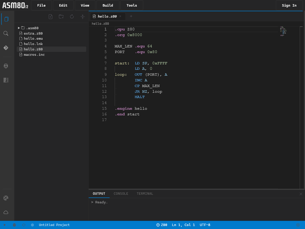
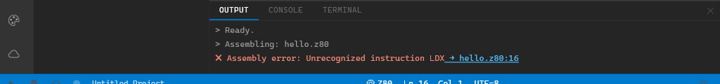
These extensions are recognised as assembly source and receive full IDE support: syntax highlighting, hover tooltips for instructions and directives, go-to-definition for labels, and the Compile button (F9).

Extension CPU / Dialect
.asm Generic (CPU set by .cpu directive or engine)
.z80 Zilog Z80
.a80 Intel 8080
.a08 Intel 8008
.a65 MOS 6502
.a68 Motorola 6800 / 6801
.a09 .h09 Motorola 6809
.816 WDC 65816
.1802 RCA CDP 1802
.z180 Zilog Z180
.a03 Motorola 6803
.s50 Signetics 2650
.a83 Sharp SM83 (LR35902)
.inc Include file (inherits CPU from parent)

Files with any of these extensions also show the Upload to hardware button when a Web Serial port is configured.


Configuration files

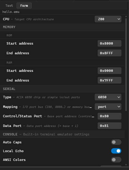
.emu — Emulator configuration

Opened with a Text / Form toggle. The form editor provides structured fields for hardware configuration sections:

Section Purpose
cpu: CPU type, clock frequency, entry point
memory: ROM/RAM regions with addresses and optional file mappings
serial: UART parameters (baud rate, port address)
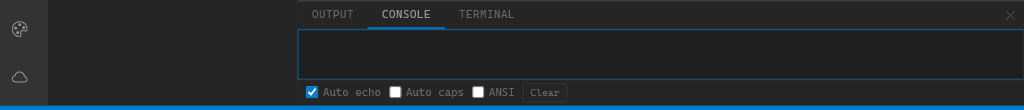
console: Software console settings
terminal: Web Serial terminal connection

When a source file contains .engine <name>, the IDE also looks for <name>.emu in the project root to load the hardware configuration automatically.

→ See .emu Files

.lnk — Linker recipe

Opened with a Text / Form toggle. Describes which object modules to link, how to map segments to memory, and what output format to produce.

→ See Linker Recipe

.lbr — Library recipe

Opened with a Text / Form toggle and also shows the Library Viewer panel when compiled. Lists the object modules that should be packed into a .lib* library archive.

→ See Library Recipe


Assembler output files

.hex / .ihex — Intel HEX

Text format representing machine code as ASCII hex records. Opens in the editor with code highlighting. When a .hex file (or a source file that would produce one) is active and a Web Serial port is configured, the Upload to Hardware button appears in the toolbar.

→ See Upload to Hardware

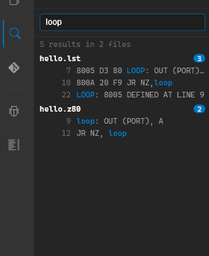
.lst — Assembler listing

Plain text listing generated alongside the compiled output. Shows each source line with its assembled bytes and addresses. Opens in the editor.

.s19 / .srec — Motorola S-Record

Text format similar to Intel HEX. Generated by the S-Record export tool. Opens in the editor.

.obj80 .objz80 .obj65 .obj816 .obj68 .obj09 .objh09 .obj08 .obj18 .objz180 .obj03 .obj50 .obj83 — Relocatable object

Binary file produced by the assembler when compiling a .module source. Opens in the OBJ Viewer which decodes: module name, defined symbols with values, segment list (CSEG/DSEG/BSSEG/ESEG), and the relocation table.

→ See Object File Viewer

.lib80 .libz80 .lib65 .lib816 .lib68 .lib09 .libh09 .lib08 .lib18 .libz180 .lib03 .lib50 .lib83 — Library archive

Binary archive of multiple object modules. Opens in the Library Viewer which lists the contained modules and their exported symbols.

→ See Library Viewer


Tape and snapshot files

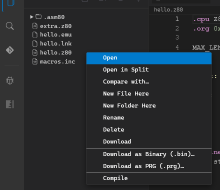
These extensions open in specialised viewers instead of the editor. They also appear in the right-click context menu of the file tree with emulator-specific actions.

.pmd — PMD-85 tape recording

Single-block or multi-block tape recording captured by the PMD-85 emulator’s Record function. Internal format: MGF (Magnetic tape Format) blocks.

Opens as: Tape Viewer — shows block table (block number, name, type, load address, size) and an editable label. The Load in emulator button loads the tape into a running PMD-85 instance.

Context menu: Open in PMD-85

→ See PMD-85 Tape

.ptp — PMD-85 PTP tape archive

Multi-block tape image, typically used for distributing software collections. Contains many MGF blocks with a 2-byte length prefix before each.

Opens as: PTP Manager — interactive table with drag-to-reorder, block delete, Save/Discard buttons. The Load in emulator button starts playback from the selected block.

Context menu: Open in PMD-85

→ See PMD-85 Tape

.pmitape — PMI-80 tape recording

JSON array of T-state intervals recorded from the PMI-80 emulator’s MIC output.

Opens as: Tape Viewer

Context menu: Open in PMI-80

→ See PMI-80 Emulator

.tap — ZX Spectrum TAP tape

Standard ZX Spectrum tape format. A flat sequence of blocks, each preceded by a 2-byte length. Flag byte 0x00 = header block, 0xFF = data block.

Opens as: Tape Viewer — block table showing type (Program / Code / Number array / Character array / Data), name, length, and header parameters (autostart line or load address).

Context menu: Open in ZX Spectrum (tape)

→ See ZX Spectrum Emulator

.tzx — ZX Spectrum TZX archive

Extended ZX Spectrum tape format supporting multiple block types: standard speed (0x10), turbo speed (0x11), pause (0x20), group start/end (0x21/0x22), and text description (0x30).

Opens as: Tape Viewer — same block table as .tap, with block type shown.

Context menu: Open in ZX Spectrum (tape)

→ See ZX Spectrum Emulator

.sna — ZX Spectrum snapshot

Full machine-state snapshot. Two sizes are supported:

  • 48k: 49 179 bytes — 27-byte register header + 48 KB RAM
  • 128k: 131 103 bytes — 27-byte header + bank data + paging registers

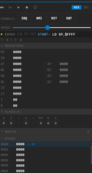
Opens as: SNA Viewer — decodes and displays all register values (AF, BC, DE, HL, IX, IY, SP, PC, I, R, alternate pairs, border, interrupt mode, IFF2, 128k banking state).

Context menu: Load snapshot in ZX Spectrum

Loading a .sna file into the ZX Spectrum emulator switches the model (48k/128k) automatically to match the snapshot size.

→ See ZX Spectrum Emulator


Binary files (Hex Viewer)

Any file whose extension is not in the text whitelist opens in the Hex Viewer — a read-only panel showing the raw bytes as a hex dump with ASCII sidebar.

Common binary extensions: .bin, .com, .prg, .rom, .img, .dat, .bmp, .dta.

Export tools can produce .bin, .com, .prg, and .sna directly from the assembler output.

→ See Binary Exports


Internal / system files

These files live in the .asm80/ hidden folder at the project root and are managed automatically by the IDE. They are excluded from ZIP exports and remote sync.

Path Purpose
.asm80/session.json Open tab list — restored when the project is next opened
.asm80/remote.json Remote project URL and sync state